- ASIC
- バッテリー マネージメントIC
- クロックとタイミングソリューション
- ESDおよびサージ保護デバイス
- 自動車用イーサネット
- 評価ボード
- 高信頼性(HiRel)
- アイソレーター
- メモリ
- マイクロコントローラー
- パワー
- RF
- セキュリティ ソリューションおよびスマートカードソリューション
- センサー技術
- 小信号トランジスタおよびダイオード
- トランシーバー
- ユニバーサル シリアル バス(USB)
- ワイヤレス接続
- Search Tools
- Technology
- Packages
- Product Information
- ご注文
- 概要
- 組込みフラッシュIPソリューション
- フラッシュプラスRAM MCPソリューション
- F-RAM (強誘電体RAM)
- NORフラッシュ
- nvSRAM (不揮発性 SRAM)
- PSRAM – 擬似スタティックRAM
- 耐放射線・高信頼性メモリ
- SRAM (スタティック RAM)
- ウェーハおよびダイメモリソリューション
- 概要
- 32ビットFM Arm® Cortex® マイクロコントローラー
- 32ビットAURIX™ TriCore™マイクロコントローラー
- 32ビットPSOC™ Arm® Cortex® マイクロコントローラー
- 32ビット TRAVEO™ T2G Arm® Cortex® マイクロコントローラー
- 32ビットXMC™産業用マイクロコントローラー Arm® Cortex®-M
- レガシー マイクロコントローラー
- モーター制御SoC/SiP
- センシングコントローラー
- 概要
- AC-DC電力変換
- 従来型の車載パワートレインIC
- クラスD オーディオアンプIC
- 非接触パワー&センシングIC
- DC/DCコンバーター
- ダイオードとサイリスタ (Si/SiC)
- 窒化ガリウム(GaN)
- ゲートドライバIC
- IGBT – 絶縁ゲート型バイポーラトランジスタ
- インテリジェント パワーモジュール (IPM)
- LEDドライバIC
- モータードライバ
- MOSFET
- パワーモジュール
- 電源IC
- 保護および監視IC
- シリコンカーバイド (SiC)
- スマート パワー スイッチ
- ソリッドステートリレー (SSR)
- ワイヤレス充電IC
- 概要
- アンテナクロススイッチ
- アンテナチューナー
- バイアスと制御
- カプラ
- ドライバアンプ
- 耐放射線マイクロ波とRF
- ローノイズアンプ (LNA)
- 高周波ダイオード
- RFスイッチ
- RFトランジスタ
- ワイヤレス制御向けレシーバー
- 概要
- Calypso®製品
- CIPURSE™ 製品
- 非接触メモリ
- OPTIGA™の組込みセキュリティ ソリューションの詳細
- SECORA™セキュリティソリューション
- セキュリ ティコントローラー
- スマートカードモジュール
- 政府ID向けスマートソリューション
- 概要
- USB 2.0 ペリフェラル コントローラー
- USB 3.2 ペリフェラル コントローラー
- USB ハブ コントローラー
- USB PD高電圧マイクロコントローラー
- USB-C AC-DC および DC-DC 充電ソリューション
- USB-C充電ポートコントローラー
- USB-Cパワーデリバリー コントローラー
- 概要
- AIROC™ オートモーティブワイヤレス
- AIROC™ Bluetooth®およびマルチプロトコル
- AIROC™ コネクトテッドMCU
- AIROC™ Wi-Fi + Bluetooth®コンボ
- 概要
- FM0+ 32ビット Arm® Cortex®-M0+ マイクロコントローラー (MCU)
-
FM3 32ビットArm® Cortex-M3®マイクロコントローラー (MCU) ファミリー
- 概要
- FM3 CY9AFx1xKシリーズ Arm® Cortex®-M3マイクロコントローラー (MCU)
- FM3 CY9AFx1xL/M/N シリーズ Arm® Cortex®-M3マイクロコントローラー (MCU)
- FM3 CY9AFx2xK/L シリーズ Arm® Cortex®-M3マイクロコントローラー (MCU)
- FM3 CY9AFx3xK/L シリーズ 超低リーク Arm® Cortex®-M3マイクロコントローラー (MCU)
- FM3 CY9AFx4xL/M/N シリーズ 低消費電力 Arm® Cortex®-M3マイクロコントローラー (MCU)
- FM3 CY9AFx5xM/N/Rシリーズ 低消費電力 Arm® Cortex®-M3マイクロコントローラー (MCU)
- FM3 CY9AFxAxL/M/N シリーズ 超低リーク Arm® Cortex®-M3 マイクロコントローラー (MCU)
- FM3 CY9BFx1xN/R 高性能シリーズ Arm® Cortex®-M3マイクロコントローラー (MCU)
- FM3 CY9BFx1xS/T 高性能シリーズ Arm® Cortex®-M3マイクロコントローラー (MCU)
- FM3 CY9BFx2xJシリーズ Arm® Cortex®-M3マイクロコントローラー (MCU)
- FM3 CY9BFx2xK/L/Mシリーズ Arm® Cortex®-M3マイクロコントローラー (MCU)
- FM3 CY9BFx2xS/Tシリーズ Arm® Cortex®-M3マイクロコントローラー (MCU)
- FM4 32ビットArm® Cortex-M4®マイクロコントローラー (MCU) ファミリー
- 概要
-
32 ビット TriCore™ AURIX™ – TC2x
- 概要
- AURIX™ ファミリー – TC21xL
- AURIX™ファミリー – TC21xSC (ワイヤレス充電)
- AURIX™ ファミリー – TC22xL
- AURIX™ ファミリー – TC23xL
- AURIX™ ファミリー – TC23xLA (ADAS)
- AURIX™ ファミリー – TC23xLX
- AURIX™ ファミリー – TC264DA (ADAS)
- AURIX™ ファミリー – TC26xD
- AURIX™ ファミリー – TC27xT
- AURIX™ ファミリー – TC297TA (ADAS)
- AURIX™ ファミリー – TC29xT
- AURIX™ファミリー – TC29xTT (ADAS)
- AURIX™ ファミリー – TC29xTX
- AURIX™ TC2xx (エミュレーションデバイス)
-
32 ビット TriCore™ AURIX™ – TC3x
- 概要
- AURIX™ ファミリー TC32xLP
- AURIX™ ファミリー – TC33xDA
- AURIX™ ファミリー - TC33xLP
- AURIX™ ファミリー – TC35xTA (ADAS)
- AURIX™ ファミリー – TC36xDP
- AURIX™ ファミリー – TC37xTP
- AURIX™ ファミリー – TC37xTX
- AURIX™ ファミリー – TC38xQP
- AURIX™ ファミリー – TC39xXA (ADAS)
- AURIX™ ファミリー – TC39xXX
- AURIX™ ファミリー – TC3Ex
- AURIX™ TC37xTE (エミュレーションデバイス)
- AURIX™ TC39xXE (エミュレーションデバイス)
- 32 ビット TriCore™ AURIX™ - TC4x
- 概要
- PSOC™ 4 Arm® Cortex® -M0/M0+
- PSOC™ 4 HV Arm® Cortex® -M0+
- PSOC™ 5 LP Arm® Cortex® -M3
- PSOC™ 6 Arm® Cortex®-M4 / M0+
- PSOC™マルチタッチタッチスクリーンコントローラー
- PSOC™ Control C3 Arm® Cortex®-M33
- 自動車用PSOC™ 4 Arm® Cortex®-M0/M0+
- PSOC™ Edge Arm® Cortex® M55/M33
- 概要
- ボディ用32ビットTRAVEO™T2G Arm® Cortex®
- クラスター用の 32 ビット TRAVEO™ T2G Arm® Cortex®
- 概要
- 32ビットXMC1000産業用マイクロコントローラー Arm® Cortex®-M0
- Cortex-M4® Arm® 32ビットXMC4000産業用マイクロコントローラー
- XMC5000産業用マイクロコントローラーArm® Cortex® -M4F
- 32ビットXMC7000産業用マイクロコントローラー Arm® Cortex®-M7®
- 概要
- 整流ブリッジおよびACスイッチ
- CoolSiC™ ショットキーダイオード
- ダイオードベアダイ
- Si ダイオード
- サイリスタ/ダイオード パワーモジュール
- サイリスタソフトスタータモジュール
- サイリスタ / ダイオードディスク
- 概要
- 車載ゲートドライバ IC
- ガルバニック絶縁型ゲートドライバ
- GaN HEMT用ゲートドライバIC
- ハイサイドゲートドライバ
- レベルシフト
- ローサイド ドライバ
- トランスドライバIC
- 概要
- BLDCモータードライバ
- BDCモータードライバ
- ステッピングモーターおよびサーボモーター ドライバ
- MCU搭載モータードライバ
- MOSFETを使用したブリッジドライバ
- ゲートドライバIC
- 概要
- 車載用MOSFET
- デュアルMOSFET
- MOSFET(Si&SiC)モジュール
- NチャネルデプレッションモードMOSFET
- NチャネルMOSFET
- PチャネルMOSFET
- CoolSiC™ MOSFET
- 小信号/小電力MOSFET
- 概要
- 車載用トランシーバー
- OPTIREG™リニア電圧レギュレーター (LDO)
- OPTIREG™ PMIC
- OPTIREG™スイッチャー
- OPTIREG™ システム ベーシス チップ (SBC)
- 概要
- EZ-USB™ CX3 MIPI CSI-2 to USB 5 Gbps カメラ コントローラー
- EZ-USB™ FX10 & FX5N USB 10Gbpsペリフェラルコントローラ
- EZ-USB™ FX20 USB 20 Gbpsペリフェラルコントローラー
- EZ-USB™ FX3 USB 5 Gbps ペリフェラル コントローラー
- EZ-USB™ FX3S USB 5 Gbps ペリフェラル コントローラー (ストレージ インターフェース付き)
- EZ-USB™ FX5 USB 5 Gbpsペリフェラルコントローラー
- EZ-USB™ SD3 USB 5 Gbps ストレージコントローラー
- EZ-USB™ SX3: FIFOインターフェースの USB 5 Gbps ペリフェラル コントローラー
- 概要
- EZ-PD™ CCG3 USB Type-Cポート コントローラーPD
- EZ-PD™ CCG3PA USB-C および PD
- EZ-PD™ CCG3PA-NFET USB-C PD コントローラー
- EZ-PD™ CCG7x シングルポート USB-Cパワーデリバリーおよび DC-DC コントローラー
- EZ-PD™ PAG1: 第 1 世代電源アダプター
- EZ-PD™ PAG2: 第 2 世代電源アダプター
- EZ-PD™ PAG2-PD USB-C PD コントローラー
- 概要
- EZ-PD™ ACG1F 1ポートUSB-Cコントローラー
- EZ-PD™ CCG2 USB Type-Cポート コントローラー
- EZ-PD™ CCG3PA車載用USB-Cおよびパワーデリバリーコントローラー
- EZ-PD™ CCG4 2 ポートUSB-CおよびPD
- EZ-PD™ CCG5デュアルポートおよび CCG5C シングルポート USB-C PDコントローラー
- EZ-PD™ CCG6 1ポート USB-C & PDコントローラー
- EZ-PD™ CCG6_CFP および EZ-PD™ CCG8_CFPデュアルシングルポート USB-C PD
- EZ-PD™ CCG6DFデュアルポートおよびCCG6SFシングルポートUSB-C PDコントローラー
- EZ-PD™ CCG7D車載用デュアルポートUSB-C PD + DC-DCコントローラー
- EZ-PD™ CCG7S車載用シングルポートUSB-C PDソリューション (DC-DCコントローラーおよびFET内蔵)
- EZ-PD™ CCG8デュアル シングル ポートUSB-C PD
- EZ-PD™ CMG1 USB-C EMCAコントローラー
- 拡張パワーレンジ (EPR) 搭載EZ-PD™ CMG2 USB-C EMCA
- 最新情報
- 航空宇宙および防衛
- AIとデータセンター
- 自動車
- 通信
- 民生用電子機器
- ヘルスケアとライフスタイル
- 家電製品
- 産業用アプリケーション
- 再生可能エネルギー
- ロボティックス
- セキュリティソリューション
- スマートホームとスマートビルディング
- ソリューション
- 概要
- 電源アダプターと充電器
- スマートテレビ向けの完全なシステムソリューション
- モバイルデバイスとスマートフォンソリューション
- マルチコプターとドローン
- 電動工具
- ホームエンターテインメント アプリケーション向けの半導体ソリューション
- スマート会議システム
- 概要
- Digital health
- 資産管理の追跡
- バッテリーの形成とテスト
- 電動フォークリフト
- バッテリー蓄電 (BESS)
- EV充電
- 高電圧ソリッドステート配電
- 産業用オートメーション
- 産業用モータードライブおよび制御
- 産業用ロボット
- LED 照明システムの設計
- 小型電気自動車ソリューション
- 電動工具
- 送配電
- トラクション
- 無停電電源装置 (UPS)
- Digital health
- 概要
- バッテリーの形成とテスト
- EV充電
- 水素
- 太陽光発電
- 風力
- ソリッドステート サーキット ブレーカー (SSCB)
- バッテリー蓄電 (BESS)
- 概要
- デバイス認証とブランド保護
- モノのインターネット (IoT) 向けの組み込みセキュリティ
- eSIM アプリケーション
- 公的身分証明書
- モバイルセキュリティ
- 決済ソリューション
- アクセス管理および発券ソリューション
- 概要
- 家庭用ロボット
- 空調システム (HVAC)
- ホームオートメーションとビルオートメーション
- PCアクセサリ
- ホームエンターテインメント アプリケーション向けの半導体ソリューション
- 概要
- 車載用補助システム
- 車載ゲートウェイ
- 車載用パワー分配システム
- ボディコントロールモジュール(BCM)
- コンフォート&コンビニエンス エレクトロニクス
- ゾーンDC-DCコンバーター 48 V~12 V
- ゾーンコントロールユニット
- 概要
- アクティブサスペンションコントロール
- 車載用ブレーキング ソリューション
- 車載用ステアリング ソリューション
- シャーシ ドメイン制御
- 最新情報
- デジタル ドキュメンテーション
- 評価ボード
- ファインダー & セレクション ツール
- プラットフォーム
- サービス
- インフィニオン オンライン パワー シミュレーション プラットフォーム
- ソフトウェア
- ツール
- パートナー
- インフィニオン フォー メーカーズ
- ユニバーシティ アライアンス プログラム
- 概要
- AIROC™ ソフトウェアとツール
- AURIX™のツールとソフトウェア
- 自動車ソフトウェア開発用のDRIVECORE
- iMOTION™ ツールとソフトウェア
- インフィニオンのスマートパワースイッチおよびゲートドライバ ツールスイート
- MOTIX™ ソフトウェア&ツール
- OPTIGA™ ツールとソフトウェア
- PSOC™ ソフトウェアとツール
- TRAVEO™ ソフトウェアとツール
- XENSIV™ツールおよびソフトウェア
- XMC™ ツールとソフトウェア
- 概要
- IPOSIM オンライン パワー シミュレーション プラットフォーム
- CoolGaN™シミュレーションツール(PLECS)
- HiRel フィット レート ツール
- IPOSIM オンライン パワー シミュレーション プラットフォーム
- インフィニオン デザイナー
- インタラクティブな製品シート
- IPOSIM オンライン パワー シミュレーション プラットフォーム
- InfineonSpiceオフラインシミュレーションツール
- OPTIREG™ 車載電源IC シミュレーションツール (PLECS)
- パワーMOSFETシミュレーション モデル
- PowerEsimスイッチモード電源設計ツール
- ソリューションファインダー
- XENSIV™磁気センサー シミュレーション ツール
- 概要
- AURIX™認証
- AURIX™開発ツール
- AURIX™組込みソフトウェア
- AURIX™マイクロコントローラーキット
- 概要
- CAPSENSE™コントローラー コンフィギュレーション ツール EZ-Click
- DC-DC統合POL電圧レギュレーター設定ツール – PowIRCenter
- EZ-USB™ SX3コンフィギュレーション ユーティリティ
- FM+ コンフィギュレーション ツール
- FMx設定ツール
- トランシーバーICコンフィギュレーション ツール
- USB EZ-PD™コンフィギュレーション ユーティリティ
- USB EZ-PD™コンフィギュレーション ユーティリティ
- USB EZ-USB™ HX3C Blaster Plusコンフィギュレーション ユーティリティ
- USB UARTコンフィギュレーション ユーティリティ
- XENSIV™タイヤ空気圧センサーのプログラミング
- 概要
- EZ-PD™ CCGx Dock ソフトウェア開発キット
- FMx Softune IDE
- ModusToolbox™ ソフトウェア
- PSOC™ ソフトウェア
- レーダー開発キット
- 錆
- USBコントローラーSDK
- ワイヤレス接続 Bluetooth メッシュヘルパー アプリケーション
- XMC™ DAVE™ソフトウェア
- 概要
- AIROC™ Bluetooth® Connect Appアーカイブ
- Cypress™ Programmerのアーカイブ
- EZ-PD™ CCGx 電力ソフトウェア開発キットのアーカイブ
- ModusToolbox™ ソフトウェアのアーカイブ
- PSOC™ Creatorのアーカイブ
- PSOC™ Designerのアーカイブ
- PSOC™ Programmerのアーカイブ
- USB EZ-PD™コンフィギュレーション ユーティリティ アーカイブ
- USB EZ-PD™ホストSDKのアーカイブ
- USB EZ-USB™ FX3のアーカイブ
- EZ-USB™ HX3PD コンフィギュレーション ユーティリティ
- WICED™ Smart SDKのアーカイブ
- WICED™ Studioのアーカイブ
- 最新情報
- サポート
- トレーニング
- 開発者コミュニティ
- News
ビジネス&財務プレス
2026/04/07
ビジネス&財務プレス
2026/03/30
ビジネス&財務プレス
2026/03/10
ビジネス&財務プレス
2026/03/09
- 会社概要
- 私たちのストーリー
- イベント
- プレス
- 投資家向け情報
- 採用情報
- 品質
- 最新ニュース
ビジネス&財務プレス
2026/04/07
ビジネス&財務プレス
2026/03/30
ビジネス&財務プレス
2026/03/10
ビジネス&財務プレス
2026/03/09
これは機械翻訳されたコンテンツです。 詳しくは こちらをご覧ください。
60 GHz レーダー搭載スマート電波センサー モジュール
人感センサーや存在検知に最適な、60 GHzミリ波レーダーセンサーを搭載したモジュール。世界最小レベルのサイズで制御・信号処理用MCUも搭載。そのまま使えるソフトウェアも提供中。技適認定取得済みでスピーディーな開発が可能。

#MakeIoTworkポッドキャスト:
存在検知や人感センサーなどwithコロナ時代のシステムを実現する60 GHzレーダー モジュールを日清紡マイクロデバイス社と共同開発。
この世界最小クラスのレーダー モジュールの背景やどんなことができるようになるのか、お話を伺っていきたいと思います。


[2021/11/15]
本モジュールが ET & IoT AWARD 2021の「IoT Technology優秀賞」を受賞しました!
人流検知や見守り(安全確認)を高精度で行える点や、使いやすさ(技適認定済み・小型モジュール化)などが評価されての受賞となりました。

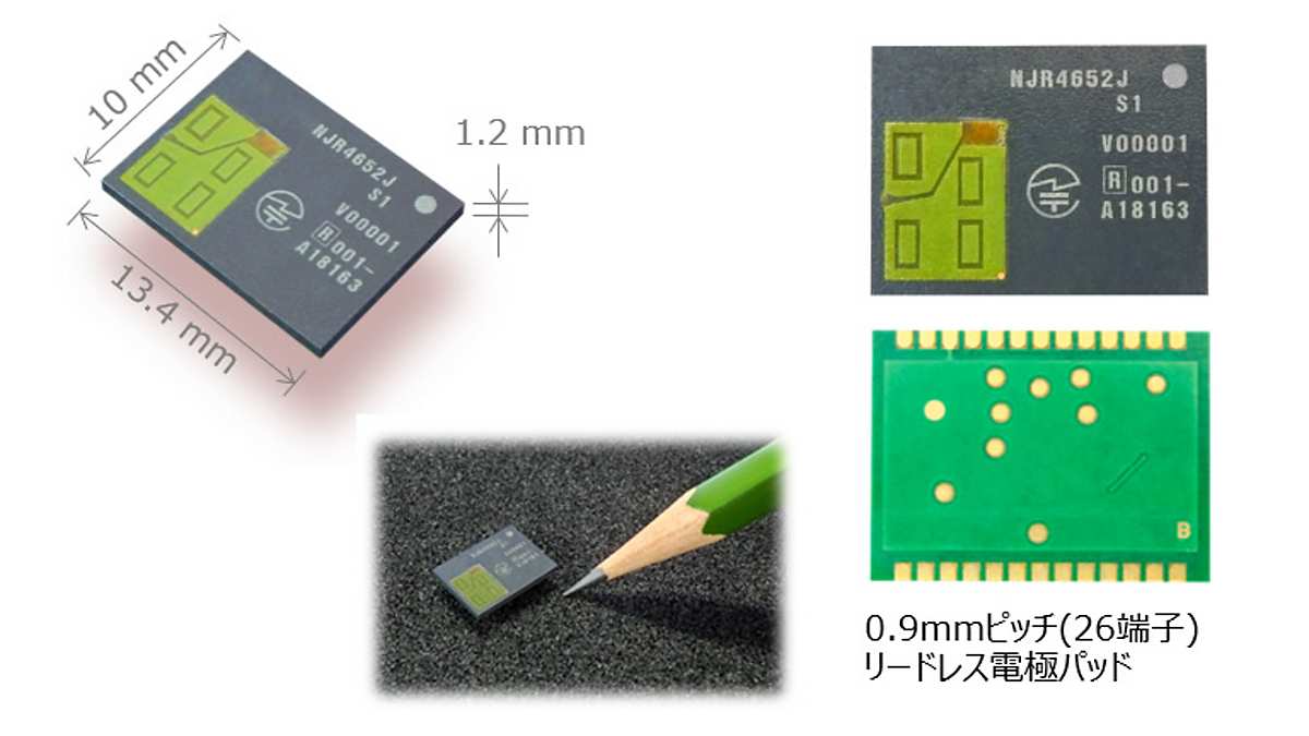

10x13.4x1.2mmのICライクな超小型パッケージにインフィニオン製60GHzミリ波レーダセンサICと制御・信号処理用MCUを内蔵し、日本国内で利用可能な技術基準適合認定を取得した世界最小レベルのセンサモジュールです(型番名:NJR4652 シリーズ)。
ターンキーソリューションとして、インフィニオンが提供するSmart Entrance Counter SolutionとPresence Detectionが利用できます。存在検知や人感センサのアプリケーション開発に最適です。
特長
- 60GHz帯ミリ波センサモジュール
- インフィニオン製レーダーセンサIC搭載
- RF制御・信号処理用MCU内蔵
- SMT対応超小型モジュール10 x 13.4 x 1.2 mm3
- アンテナ構成 - 1・TX / 3・RX
- 製品単体で技術基準適合認定取得
インフィニオンが用意する2種類の人感センサアプリケーションが利用可能です。
プログラミングは不要ですぐに使用できます。

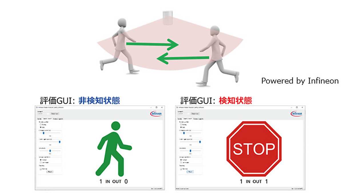

エントランス等での入退出の頻度を検出できます。進入と退出を個別に識別することができるため、高機能なエントランスセンサとして利用できます
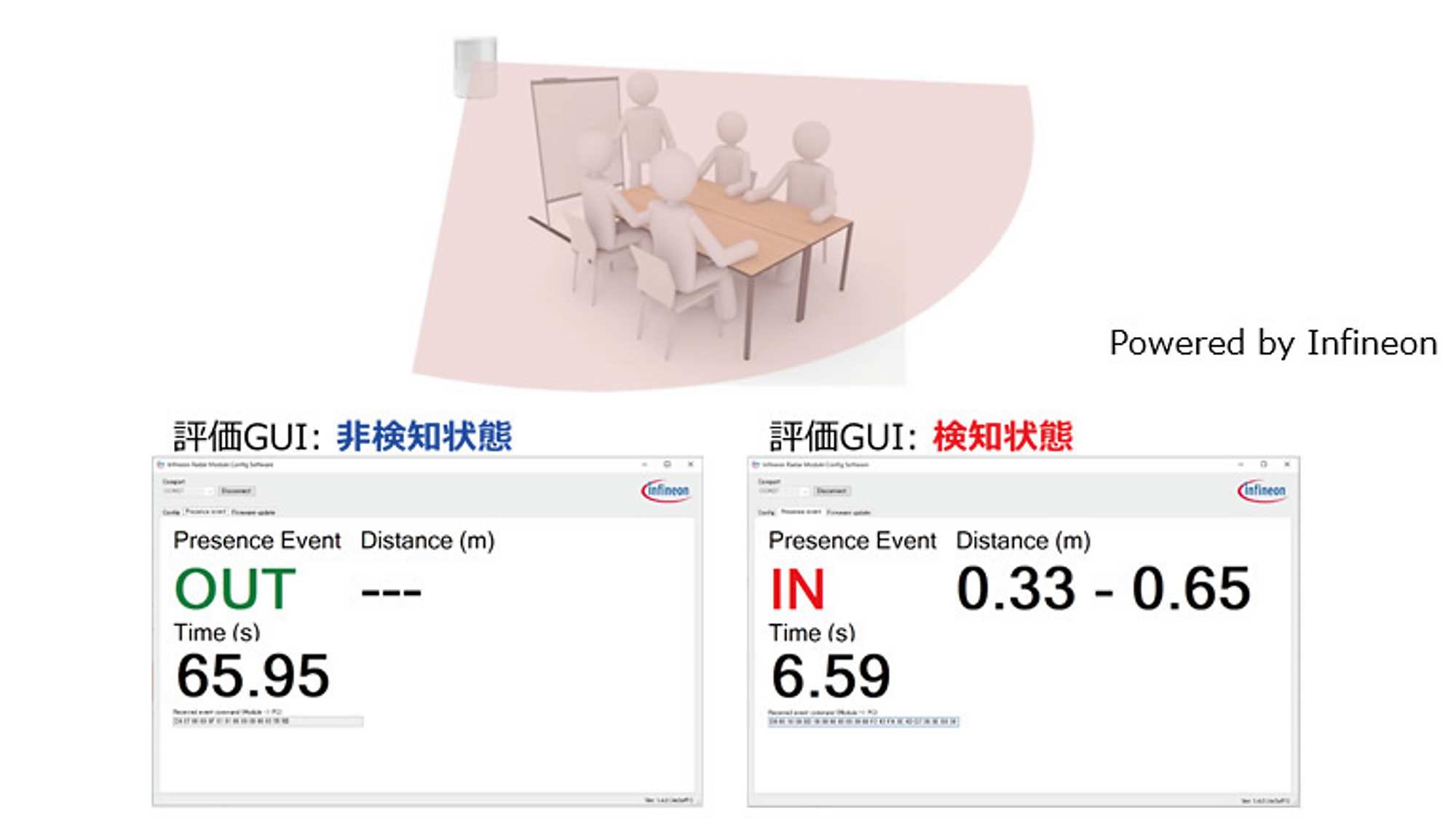


オフィスや会議室等での人の有無(存在)を検出できます。静止している人も検出することが可能です。検出対象までの距離情報も得ることができます。


図のモジュール評価ツールを提供します。PCがあればすぐに評価開始可能です。
- モジュール実装済みインターポーザ基板
- USBインターフェイス用基板(インターポーザ基板を接続)
- 評価用ソフトウェア(GUI)
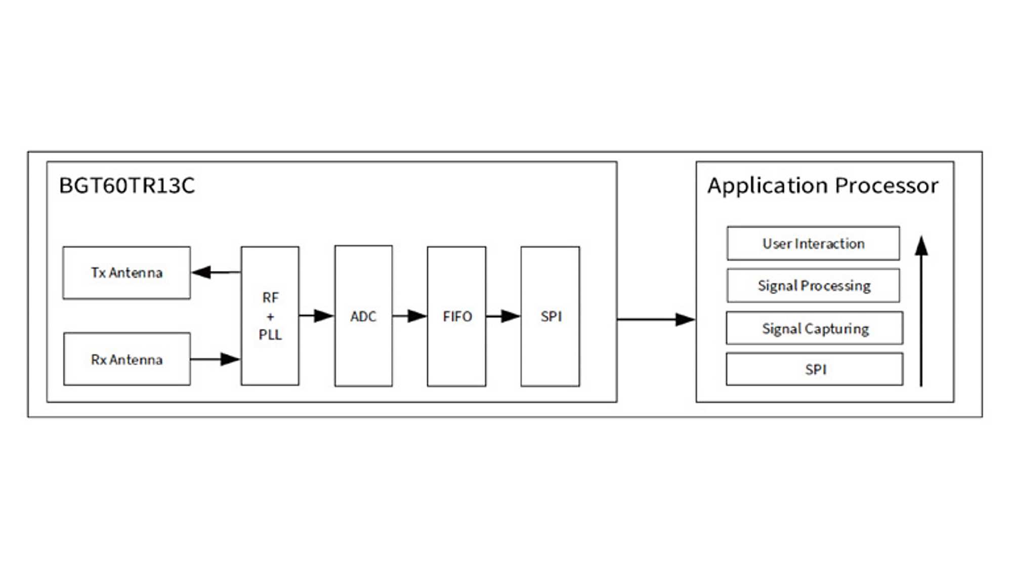
システムの概要
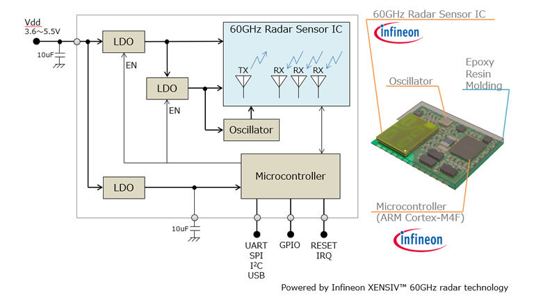
BGT60TR13Cは、1つの送信アンテナ(TX)からFMCW信号を出力し、3つの受信アンテナ(RX)で対象物からのエコー信号を受信します。
また、受信アンテナ毎にベースバンドフィルタ、VGAおよびADCを持ちます。これらによりデジタル化した受信信号を出力します。
出力信号はアプリケーションプロセッサ(AP)に渡されます.
つまり、標準的なセンサシステムでは下記の構成となります(下図参照)。
- BGT60TR13C : RF信号、送信・受信の制御及び、サンプリングされた受信信号(レーダ信号)の出力
- アプリケーションプロセッサ(AP) : レーダ信号を用いた各種信号処理とユーザインターフェース、外部機器との通信処理

特長
- FMCW方式60GHzレーダーセンサー
- 5.5GHz帯域幅
- パッケージ内アンテナ内蔵 (1xTX, 3xRX)
- 自律制御可能なシステム構成
- 動作設定とレーダー信号用のデジタルインターフェース
- 低電力動作可能
仕様
*Power Supply特性及びRF特性はソフトウェア仕様に依存します
端子情報


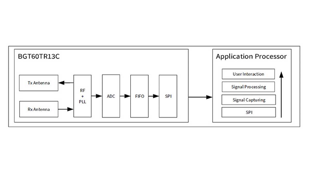
システムの概要
BGT60TR13Cは、1つの送信アンテナ(TX)からFMCW信号を出力し、3つの受信アンテナ(RX)で対象物からのエコー信号を受信します。
また、受信アンテナ毎にベースバンドフィルタ、VGAおよびADCを持ちます。これらによりデジタル化した受信信号を出力します。
出力信号はアプリケーションプロセッサ(AP)に渡されます.
つまり、標準的なセンサシステムでは下記の構成となります(下図参照)。
- BGT60TR13C : RF信号、送信・受信の制御及び、サンプリングされた受信信号(レーダ信号)の出力
- アプリケーションプロセッサ(AP) : レーダ信号を用いた各種信号処理とユーザインターフェース、外部機器との通信処理
特長
- FMCW方式60GHzレーダーセンサー
- 5.5GHz帯域幅
- パッケージ内アンテナ内蔵 (1xTX, 3xRX)
- 自律制御可能なシステム構成
- 動作設定とレーダー信号用のデジタルインターフェース
- 低電力動作可能
仕様
*Power Supply特性及びRF特性はソフトウェア仕様に依存します
端子情報