
- ASIC
- Battery management ICs
- Clocks and timing solutions
- ESD and surge protection devices
- Automotive Ethernet
- Evaluation Boards
- High reliability
- Isolation
- Memories
- Microcontroller
- Power
- RF
- Security and smart card solutions
- Sensor technology
- Small signal transistors and diodes
- Transceivers
- Universal Serial Bus (USB)
- Wireless connectivity
- Search Tools
- Technology
- Packages
- Product Information
- Ordering
- Overview
- Automotive Ethernet PHY for in-vehicle networking
- Automotive Ethernet Switches for in-vehicle networking
- Overview
- Embedded flash IP solutions
- Flash+RAM MCP solutions
- F-RAM (Ferroelectric RAM)
- NOR flash
- nvSRAM (non-volatile SRAM)
- PSRAM – Pseudostatic RAM
- Radiation hardened and high-reliability memories
- SRAMs (Static Random Access Memory)
- Wafer and die memory solutions
- Overview
- AURIX™ TriCore™ MCUs
- PSOC™ MCUs
- TRAVEO™ T2G MCUs
- XMC™ MCUs
- Legacy MCUs
- MOTIX™ motor control SoCs/SIPs
- AURIX™ RC1 MCUs
- Overview
- AC-DC power conversion
- Automotive conventional powertrain ICs
- Class D audio amplifier ICs
- Contactless power and sensing ICs
- DC-DC converters
- Diodes and thyristors (Si/SiC)
- eFuses
- Gallium nitride (GaN)
- Gate Driver ICs
- IGBTs – Insulated gate bipolar transistors
- Intelligent power modules (IPM)
- JFETs
- LED driver ICs
- Motor drivers
- MOSFETs
- Power modules
- Power supply ICs
- Protection and monitoring ICs
- Silicon carbide (SiC)
- Smart power switches
- Solid state relays and isolators
- Wireless charging ICs
- Overview
- Antenna cross switches
- Antenna tuners
- Bias and control
- Coupler
- Driver amplifiers
- Rad hard microwave and RF
- Low noise amplifiers (LNAs)
- RF diode
- RF switches
- RF transistors
- Wireless control receiver
- Overview
- Calypso® products
- CIPURSE™ products
- Contactless memories
- OPTIGA™ embedded security solutions
- SECORA™ security solutions
- Security controllers
- Smart card modules
- Smart solutions for government ID
- Overview
- ToF 3D image sensors
- Current sensors
- Gas sensors
- Inductive position sensors
- MEMS microphones
- Pressure sensors
- Radar sensors
- Magnetic position sensors
- Magnetic speed sensors
- Capacitive sensors
- Temperature sensors
- Battery sensors
- Digital X-ray
- Computed tomography
- Sensor interface ASICs
- Overview
- Bipolar transistors
- Diodes
- Small signal/small power MOSFET
- Overview
- Automotive transceivers
- Control communication
- Powerline communications
- Overview
- USB 2.0 peripheral controllers
- USB 3.2 peripheral controllers
- USB hub controllers
- USB PD high-voltage microcontrollers
- USB-C AC-DC and DC-DC charging solutions
- USB-C charging port controllers
- USB-C Power Delivery controllers
- Overview
- AIROC™ Automotive wireless
- AIROC™ Bluetooth® and multiprotocol
- AIROC™ connected MCU
- AIROC™ Wi-Fi + Bluetooth® combos
- AIROC™ Ultra-Wide Band Solutions
- Overview
- Commercial off-the-shelf (COTs) memory portfolio
- Defense memory portfolio
- High-reliability power conversion and management
- Overview
- Rad hard microwave and RF
- Radiation hardened power
- Space memory portfolio
- Overview
- Parallel NOR flash memory
- SEMPER™ NOR flash family
- SEMPER™ X1 LPDDR flash
- Serial NOR flash
- Overview
-
AURIX™ TC2x - 32-bit TriCore™
- Overview
- AURIX™ family – TC21xL
- AURIX™ family – TC21xSC (wireless charging)
- AURIX™ family – TC22xL
- AURIX™ family – TC23xL
- AURIX™ family – TC23xLA (ADAS)
- AURIX™ family – TC23xLX
- AURIX™ family – TC264DA (ADAS)
- AURIX™ family – TC26xD
- AURIX™ family – TC27xT
- AURIX™ family – TC297TA (ADAS)
- AURIX™ family – TC29xT
- AURIX™ family – TC29xTT (ADAS)
- AURIX™ family – TC29xTX
- AURIX™ TC2x emulation devices
-
AURIX™ TC3x - 32-bit TriCore™
- Overview
- AURIX™ family - TC32xLP
- AURIX™ family – TC33xDA
- AURIX™ family - TC33xLP
- AURIX™ family – TC35xTA (ADAS)
- AURIX™ family – TC36xDP
- AURIX™ family – TC37xTP
- AURIX™ family – TC37xTX
- AURIX™ family – TC38xQP
- AURIX™ family – TC39xXA (ADAS)
- AURIX™ family - TC39xXX/XP
- AURIX™ family – TC3Ex
- AURIX™ TC37xTE (emulation devices)
- AURIX™ TC39xXE (emulation devices)
- AURIX™ TC4x - 32-bit TriCore™
- Overview
- PSOC™ 4 Microcontroller: Arm® Cortex®-M0/M0+
- PSOC™ 4 HV Arm® Cortex®-M0+
- PSOC™ 5 LP Arm® Cortex®-M3
- PSOC™ 6 Arm® Cortex®-M4/M0+
- PSOC™ Multitouch Touchscreen Controller
- PSOC™ Control C3 Arm® Cortex®-M33
- PSOC™ Automotive 4: Arm® Cortex®-M0/M0+
- PSOC™ Edge Arm® Cortex® M55/M33
- PSOC™ Control C1 Arm® Cortex®-M0
- Overview
- 32-bit TRAVEO™ T2G Arm® Cortex® for body
- 32-bit TRAVEO™ T2G Arm® Cortex® for cluster
- Overview
- 32-bit XMC1000 industrial microcontroller Arm® Cortex®-M0
- 32-bit XMC4000 industrial microcontroller Arm® Cortex®-M4
- XMC5000 Industrial Microcontroller Arm® Cortex®-M4F
- 32-bit XMC7000 Industrial Microcontroller Arm® Cortex®-M7
- Overview
- Legacy 32-bit MCU
- Legacy 8-bit/16-bit microcontroller
- Other legacy MCUs
- 32-bit FM Arm® Cortex® Microcontroller
- Sensing controllers
- Overview
- AC-DC integrated power stage - CoolSET™
- AC-DC PWM and PFC controller
- Overview
- Bridge rectifiers & AC switches
- CoolSiC™ Schottky diodes
- Diode bare dies
- Power stacks
- Silicon diodes
- Thyristor / Diode Power Modules
- Thyristor soft starter modules
- Thyristor/diode discs
- Overview
- GaN bidirectional switches
- GaN smart
- GaN transistors (GaN HEMTs)
- GaN with integrated driver
- GaN bare dies
- Overview
- Automotive gate driver ICs
- Gate Driver ICs for GaN HEMTs
- Gate Driver ICs for SiC MOSFETs
- Half-Bridge Gate Driver ICs
- High-Side Gate Driver ICs
- Isolated Gate Driver ICs
- Level-Shift Gate Driver ICs
- Low-Side Gate Driver ICs
- Three-Phase Gate Driver ICs
- Transformer Driver ICs
- Overview
- AC-DC LED driver ICs
- Ballast IC
- DC-DC LED driver IC
- LED dimming interface IC
- Linear LED driver IC
- LITIX™ - Automotive LED Driver IC
- NFC wireless configuration IC with PWM output
- VCSEL driver
- Overview
- BLDC motor drivers
- BDC motor drivers
- Stepper & servo motor drivers
- Motor drivers with MCU
- Bridge drivers with MOSFETs
- Gate Driver ICs
- Overview
- Automotive MOSFET: 30 V to 800 V
- Dual MOSFETs
- MOSFET (Si & SiC) Modules
- N-channel depletion mode MOSFET
- N-channel MOSFETs
- P-channel MOSFETs
-
Silicon carbide CoolSiC™ MOSFETs
- Overview
- Silicon Carbide MOSFET modules
- Silicon carbide MOSFET discretes
- Silicon carbide MOSFETs bare dies
- Silicon Carbide Bidirectional Switches
- 400 V / 440 V Silicon Carbide MOSFETs
- 650 V Silicon Carbide MOSFETs
- 750 V Silicon Carbide MOSFETs
- 1200 V Silicon Carbide MOSFETs
- 1700 V Silicon Carbide MOSFETs
- 2000 V Silicon Carbide MOSFETs
- 2300 V Silicon Carbide MOSFETs
- 3300 V Silicon Carbide MOSFETs
- Small signal/small power MOSFET
- Current Sensing MOSFETs
- Overview
- IGBT modules
- MOSFET (Si & SiC) Modules
- Intelligent power modules (IPM)
- Diodes and thyristors (Si/SiC)
- Automotive IGBT and CoolSiC™ MOSFET modules
- High density power modules
- Overview
- Automotive transceivers
- Linear voltage regulators
- Power management ICs (PMIC)
- Automotive switching regulators
- System Basis Chips (SBC)
- Overview
- High-side switches
- Low-side switches
- Multichannel SPI Switches & Controller
- Automotive eFuses
- Overview
- Radar sensors for automotive
- Radar sensors for IoT
- Overview
- EZ-USB™ CX3 MIPI CSI2 to USB 3.0 camera controller
- EZ-USB™ FX10 & FX5N USB 10Gbps peripheral controller
- EZ-USB™ FX20 USB 20 Gbps peripheral controller
- EZ-USB™ FX3 USB 5 Gbps peripheral controller
- EZ-USB™ FX3S USB 5 Gbps peripheral controller with storage interface
- EZ-USB™ FX5 USB 5 Gbps peripheral controller
- EZ-USB™ SD3 USB 5 Gbps storage controller
- EZ-USB™ SX3 FIFO to USB 5 Gbps peripheral controller
- Overview
- EZ-PD™ PMG1-B1 Battery Charge Controller with USB-C PD MCU
- EZ-PD™ PMG1-S0 high-voltage MCU with USB-C and PD
- EZ-PD™ PMG1-S1 high-voltage MCU with USB-C and PD
- EZ-PD™ PMG1-S2 high-voltage MCU with USB PD
- EZ-PD™ PMG1-S3 high-voltage MCU with USB-C & PD
- EZ-PD™ PMG1-B2 Battery Charge Controller with USB-C PD MCU
- Overview
- EZ-PD™ CCG3 USB type-C port controller PD
- EZ-PD™ CCG3PA USB-C and PD
- EZ-PD™ CCG3PA-NFET USB-C PD controller
- EZ-PD™ CCG7x consumer USB-C Power Delivery & DC-DC controller
- EZ-PD™ PAG1: power adapter generation 1
- EZ-PD™ PAG2: Power Adapter Generation 2
- EZ-PD™ PAG2-PD USB-C PD Controller
- Overview
- EZ-PD™ ACG1F one-port USB-C controller
- EZ-PD™ CCG2 USB Type-C port controller
- EZ-PD™ CCG3PA Automotive USB-C and Power Delivery controller
- EZ-PD™ CCG4 two-port USB-C and PD
- EZ-PD™ CCG5 dual-port and CCG5C single-port USB-C PD controllers
- EZ-PD™ CCG6 one-port USB-C & PD controller
- EZ-PD™ CCG6_CFP and EZ-PD™ CCG8_CFP Dual-Single-Port USB-C PD
- EZ-PD™ CCG6DF dual-port and CCG6SF single-port USB-C PD controllers
- EZ-PD™ CCG7D Automotive dual-port USB-C PD + DC-DC controller
- EZ-PD™ CCG7S Automotive single-port USB-C PD solution with a DC-DC controller + FETs
- EZ-PD™ CCG8 dual-single-port USB-C PD
- EZ-PD™ CMG1 USB-C EMCA controller
- EZ-PD™ CMG2 USB-C EMCA controller with EPR
Browse by core architecture
Browse by key technologies
Browse by design resources & partners
- LATEST IN
- Aerospace and defense
- AI and data center
- Automotive
- Communications
- Consumer electronics
- Industrial
- Security solutions
- Smart home and building
- Solutions
- Overview
- Defense applications
- Space applications
- Overview
- Data center power solutions
- Edge computing
- Machine Learning Edge AI
- Overview
- ADAS & autonomous driving
- Automotive body electronics
- Automotive LED lighting systems
- Automotive zonal architecture
- Chassis control & safety
- Electric vehicle drivetrain system
- EV thermal management system
- In-vehicle infotainment & HMI
- Light electric vehicle solutions
- Overview
- Satellite communications
- Telecommunications infrastructure
- Overview
- PC accessories
- AR and smart glasses
- Complete system solutions for smart TVs
- Consumer wearables
- Drones
- Home appliances
- Mobile device and smartphone solutions
- Photovoltaic
- Power adapters and chargers
- Semiconductor solutions for home entertainment applications
- Smart conference systems
- Overview
- Asset Tracking
- Battery energy storage (BESS)
- Battery formation and testing
- Digital health
- Electric forklifts
- EV charging
- High voltage solid-state power distribution
- Hydrogen electrolysis
- Industrial & Medical SMPS
- Industrial automation
- Industrial motor drives and controls
- Industrial robots
- LED lighting system design
- Light electric vehicle solutions
- Photovoltaic
- Power adapters and chargers
- Power tools
- Power transmission and distribution
- Robotics
- Traction
- Uninterruptible power supplies (UPS)
- Wind power
- Overview
- Access control and ticketing
- Device authentication and brand protection
- Embedded security for the Internet of Things (IoT)
- eSIM applications
- Government identification
- Mobile security
- Payment solutions
- Overview
- Heating ventilation and air conditioning (HVAC)
- Home and building automation
- Overview
- Battery management systems (BMS)
- Connectivity
- Human Machine Interface
- Machine Learning Edge AI
- Motor control
- Power conversion
- Security
- Sensor solutions
- System diagnostics and analytics
- Overview
- Data center power distribution
- FPGAs in datacenter applications
- Power system reliability modeling
-
Server rack power management
- Overview
- AI accelerator cards
- AMD CPU voltage regulator ICs
- Ampere CPU voltage regulator ICs
- Intel CPU voltage regulator ICs
- Intermediate Bus Converter (IBC)
- Network switches for AI data centers and server racks
- Server battery backup units (BBU)
- Server power path protection
- Server power supply units (PSU)
- SmartNIC cards
- Overview
- Automotive animated LED lighting system
- Automotive LED front single light functions
- Automotive LED rear single light functions
- Full LED headlight system - multi-channel LED driver
- LED driver solutions for electric two- and three-wheelers
- LED pixel light controller - supply & communication
- Static interior ambient LED light
- Overview
- Active suspension control
- Automotive braking solutions
- Automotive steering solutions
- Chassis domain control
- Overview
-
Automotive battery management system
- Overview
- Automotive battery cell monitoring & balancing
- Automotive battery control unit (BCU)
- Automotive battery isolated communication
- Automotive battery management system (BMS) - 12 V to 24 V
- Automotive battery management system (BMS) - 48 V
- Automotive battery management system (BMS) - high-voltage
- Automotive battery pack monitoring
- Automotive battery passport & event logging
- Automotive battery protection & disconnection
- Automotive current sensing & coulomb counting
- BMS (electric two- & three-wheelers)
- Auxiliary inverter
- Auxiliary inverter - high-voltage (commercial vehicles)
- REEV engine & HV starter‑generator control
- DC-DC converter high-voltage
- DC-DC converter high-voltage (commercial vehicles)
- EV charging
- EV traction inverter
- FCEV powertrain solutions
- On-board charging (electric commercial vehicles)
- On-board charging (OBC)
- On-board charging (OBC) solutions for electric two- and three-wheelers
- Traction inverter (electric commercial vehicles)
- Traction inverter (electric two- & three-wheelers)
- Overview
- Audio amplifier solutions
- Complete system solutions for smart TVs
- Distribution audio amplifier unit solutions
- Home theater installation speaker system solutions
- Party speaker solutions
- PoE audio amplifier unit solutions
- Portable speaker solutions
- Powered active speaker systems
- Remote control
- Smart speaker designs
- Soundbar solutions
- Overview
- Data center power solutions
- Digital input/output (I/O) modules
- DIN rail power supply solutions
- Home and building automation
- Industrial HMI Monitors and Panels
- Industrial motor drives and controls
- Industrial PC
- Industrial robots
- Machine vision
- Mobile robots (AGV, AMR)
- Solid-state circuit breaker (SSCB)
- Uninterruptible power supplies (UPS)
- Overview
- Automotive battery management system
- Industrial and consumer BMS
- Overview
- AC-DC power conversion
- DC-DC power conversion
- Overview
- Power supply health monitoring
- LATEST IN
- Digital documentation
- Boards & Kits
- Finder & selection tools
- Platforms
- Services
- Simulation & Modeling
- Software
- Tools
- Partners
- Infineon for Makers
- University Alliance Program
- Overview
- Bipolar Discs Finder
- Bipolar Module Finder
- Connected Secure Systems Finder
- Diode Rectifier Finder
- ESD Protection Finder
- Evaluation Board Finder
- Gate Driver Finder
- IGBT Discrete Finder
- IGBT Module Finder
- IPM Finder
- Microcontroller Finder
- MOSFET Finder
- PMIC Finder
- Product Finder
- PSOC™ and FMx MCU Board & Kit Finder
- Radar Finder
- Reference Design Finder
- Simulation Model Finder
- Smart Power Switch Finder
- Transceiver Finder
- Voltage Regulator Finder
- Wireless Connectivity Board & Kit Finder
- Infineon Gate Driver Recommendation Tool
- Overview
- AIROC™ software & tools
- AURIX™ software & tools
- DRIVECORE™ for automotive software development
- iMOTION™ software & tools
- Infineon Smart Power Switches & Gate Driver Tool Suite
- MOTIX™ software & tools
- OPTIGA™ software & tools
- PSOC™ software & tools
- TRAVEO™ software & tools
- XENSIV™ software & tools
- XMC™ software & tools
- Overview
- HiRel Fit Rate Tool
- Infineon Designer
- Interactive product sheet
- IPOSIM Online Power Simulation Platform
- InfineonSpice Offline Simulation Tool
- OPTIREG™ automotive power supply ICs Simulation Tool (PLECS)
- Power MOSFET Simulation Models
- PowerEsim Switch Mode Power Supply Design Tool
- Solution Finder
- XENSIV™ Magnetic Sensor Simulation Tool
- Overview
- Configuration
- Hardware Development
- Programming & Testing
- SDK
- Tools Archive
- Utilities
- Overview
- AURIX™ certifications
- AURIX™ development tools
-
AURIX™ Embedded Software
- Overview
- AURIX™ Applications software
- AURIX™ Artificial Intelligence
- AURIX™ Gateway
- AURIX™ iLLD Drivers
- Infineon safety
- AURIX™ Security
- AURIX™ TC3xx Motor Control Application Kit
- AURIX™ TC4x SW application architecture
- Infineon AUTOSAR
- Communication and Connectivity
- Middleware
- Non AUTOSAR OS/RTOS
- OTA
- AURIX™ Microcontroller Kits
- Overview
- TRAVEO™ Development Tools
- TRAVEO™ Embedded Software
- Overview
- XENSIV™ Development Tools
- XENSIV™ Embedded Software
- XENSIV™ evaluation boards
- Overview
- CAPSENSE™ Controllers Code Examples
- Memories for Embedded Systems Code Examples
- PSOC™ 1 Code Examples for PSOC™ Designer
- PSOC™ 3 Code Examples for PSOC™ Creator
- PSOC™ 3/4/5 Code Examples
- PSOC™ 4 Code Examples for PSOC™ Creator
- PSOC™ 6 Code Examples for PSOC™ Creator
- PSOC™ 63 Code Examples
- USB Controllers Code Examples
- Overview
- AIROC™ Wi-Fi & Bluetooth EZ-Serial Module Firmware Platform
- AIROC™ Wi-Fi & Bluetooth Linux and Android Drivers
- emWin Graphics Library and GUI for PSOC™
- Infineon Complex Device Driver for Battery Management Systems
- Memory Solutions Hub
- PSOC™ 6 Peripheral Driver Library (PDL) for PSOC™ Creator
- USB Controllers EZ-USB™ GX3 Software and Drivers
- Overview
- CAPSENSE™ Controllers Configuration Tools EZ-Click
- DC-DC Integrated POL Voltage Regulators Configuration Tool – PowIRCenter
- EZ-USB™ SX3 Configuration Utility
- FM+ Configuration Tools
- FMx Configuration Tools
- Tranceiver IC Configuration Tool
- USB EZ-PD™ Configuration Utility
- USB EZ-PD™ Dock Configuration Utility
- USB EZ-USB™ HX3C Blaster Plus Configuration Utility
- USB UART Config Utility
- XENSIV™ Tire Pressure Sensor Programming
- Overview
- EZ-PD™ CCGx Dock Software Development Kit
-
FMx Softune IDE
- Overview
- RealOS™ Real-Time Operating System
- Softune IDE Language tools
- Softune Workbench
- Tool Lineup for F2MC-16 Family SOFTUNE V3
- Tool Lineup for F2MC-8FX Family SOFTUNE V3
- Tool Lineup for FR Family SOFTUNE V6
- Virtual Starter Kit
- Windows 10 operation of released SOFTUNE product
- Windows 7 operation of released SOFTUNE product
- Windows 8 operation of released SOFTUNE product
- Infineon GUI Designer
- ModusToolbox™ Software
- PSOC™ Creator Software
- Radar Development Kit
- RUST
- USB Controllers SDK
- Wireless Connectivity Bluetooth Mesh Helper Applications
- XMC™ DAVE™ Software
- Overview
- AIROC™ Bluetooth® Connect App Archive
- Cypress™ Programmer Archive
- EZ-PD™ CCGx Power Software Development Kit Archive
- ModusToolbox™ Software Archive
- PSOC™ Creator Archive
- PSOC™ Designer Archive
- PSOC™ Programmer Archive
- USB EZ-PD™ Configuration Utility Archives
- USB EZ-PD™ Host SDK Archives
- USB EZ-USB™ FX3 Archive
- USB EZ-USB™ HX3PD Configuration Utility Archive
- WICED™ Smart SDK Archive
- WICED™ Studio Archive
- Overview
- Infineon Developer Center Launcher
- Infineon Register Viewer
- Pin and Code Wizard
- Timing Solutions
- Wireless Connectivity
- LATEST IN
- Support
- Training
- Developer Community
- News
Business & Financial Press
Nov 09, 2026
Business & Financial Press
Nov 04, 2026
Business & Financial Press
Nov 02, 2026
Business & Financial Press
Oct 27, 2026
- Company
- Our stories
- Events
- Press
- Investor
- Careers
- Quality
- Latest news
Business & Financial Press
Nov 09, 2026
Business & Financial Press
Nov 04, 2026
Business & Financial Press
Nov 02, 2026
Business & Financial Press
Oct 27, 2026

Technology
Describes how a gate driver IC transfers a signal or isolates circuitry internally.
Topology
Describes the arrangement being driven, such as low-side, half-bridge, or three-phase.
Isolation Class
Defines the electrical separation. Half-bridge can use level-shift or isolated channels.
Technology determines how the command reaches the output stage, which electrical domains can be bridged, and how the IC behaves during fast transients.
Technology is not topology. A half-bridge describes a circuit topology, while SOI and JI describe implementation technologies. "Isolated" refers to a system architecture, whereas Coreless Transformer is the technology EiceDRIVER™ uses to provide isolation.
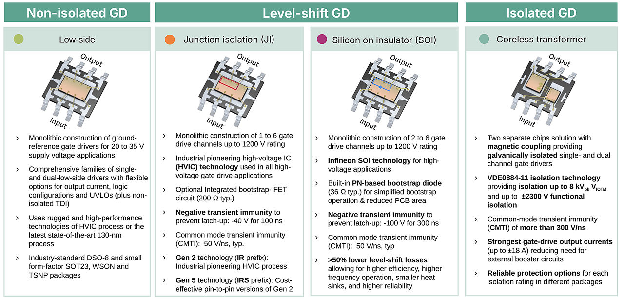
EiceDRIVER™ Gate Driver IC technologies: non-isolated low-side, junction-isolation and SOI level-shift, and coreless-transformer isolated drivers.
Infineon coreless transformer (CT) technology integrates an on-chip transformer, made of metal spirals and silicon-oxide insulation, using semiconductor manufacturing processes. The transformer transmits switching information and other signals magnetically between a separate input chip and output chip, which are galvanically isolated. The output side runs from its own isolated supply referenced to the power switch.
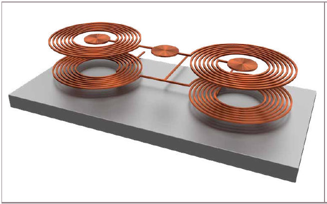
Coreless transformer: on-chip metal spirals separated by silicon-oxide insulation transfer the switching signal across the isolation barrier.
- 1- and 2-channel solutions
- Functional, basic, and reinforced isolation options
- Multiple package and family choices
- Voltage classes up to 2300 V; isolation up to 8 kVpk (VIOTM) and up to ±2300 V functional isolation
- UL 1577 certification (VISO = 5.7 kV rms) in selected packages; 4 mm and 8 mm creepage options
Galvanic separation between control and power domains
Common-mode transient immunity (CMTI) of more than 300 V/ns in selected families
Output currents up to ±18 A, reducing the need for external booster circuits
Short propagation delay and tight delay matching for driving SiC MOSFETs, GaN HEMTs, IGBTs and MOSFETs
- DESAT protection
- Active Miller clamp
- Soft-off capability
- TLTO functionality
- Slew-rate control
- I²C configurability (EiceDRIVER™ X3 Digital)
- Monitoring and diagnostic features
- Industrial drives
- Solar (PV) and energy storage
- UPS
- EV charging and on-board chargers
- Automotive traction inverters
- Server and telecom power supplies
- 1- and 2-channel solutions
- Functional, basic, and reinforced isolation options
- Multiple package and family choices
- Voltage classes up to 2300 V; isolation up to 8 kVpk (VIOTM) and up to ±2300 V functional isolation
- UL 1577 certification (VISO = 5.7 kV rms) in selected packages; 4 mm and 8 mm creepage options
Galvanic separation between control and power domains
Common-mode transient immunity (CMTI) of more than 300 V/ns in selected families
Output currents up to ±18 A, reducing the need for external booster circuits
Short propagation delay and tight delay matching for driving SiC MOSFETs, GaN HEMTs, IGBTs and MOSFETs
- DESAT protection
- Active Miller clamp
- Soft-off capability
- TLTO functionality
- Slew-rate control
- I²C configurability (EiceDRIVER™ X3 Digital)
- Monitoring and diagnostic features
- Industrial drives
- Solar (PV) and energy storage
- UPS
- EV charging and on-board chargers
- Automotive traction inverters
- Server and telecom power supplies
Next step:
Explore CT-based isolated compact, enhanced, single-channel and dual-channel isolated gate driver families, transformer drivers ICs for isolated gate driver bias supplies, and solid state isolators and relays.
Infineon silicon-on-insulator (SOI) technology is a high-voltage level-shift technology. Each transistor is isolated by a buried layer of silicon dioxide, which eliminates the parasitic bipolar transistors that can cause latch-up. SOI is used in Infineon single high-side, high- and low-side, half-bridge and three-phase gate drivers. SOI does not create a galvanic barrier between input and output, so it is used where galvanic isolation is not required, for example in motor drives, home appliances and power supplies.
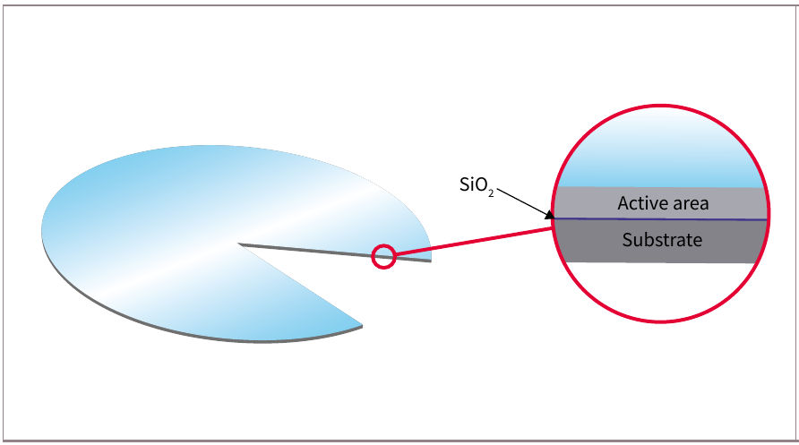
In SOI technology, a buried silicon-dioxide layer isolates the active area from the substrate.
Infineon gate drivers based on SOI technology offers:
- Monolithic construction of up to six gate-drive channels, up to 1200 V.
- An integrated PN-based bootstrap diode (36 Ω typical) that simplifies bootstrap operation and reduces PCB area.
- Negative transient immunity of −100 V for 300 ns, which prevents latch-up.
- Typical common-mode transient immunity (CMTI) of 50 V/ns.
- More than 50% lower level-shift losses, allowing higher efficiency, higher-frequency operation, smaller heat sinks and higher reliability.
- Integrated input filters for noise immunity.
Lower level-shift losses in practice: On the same PCB, at a 300 V DC bus and 300 kHz switching with CoolMOS™ P7 MOSFETs, an EiceDRIVER™ SOI half-bridge driver (2ED2106S06F) ran 55.6 °C cooler than a standard high- and low-side driver.
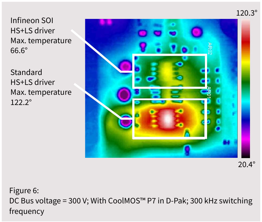
Thermal image on the same PCB at a 300 V DC bus and 300 kHz: EiceDRIVER™ SOI driver at 66.6 °C maximum versus 122.2 °C for a standard high- and low-side driver.
Next step:
Explore SOI level-shift high-voltage gate driver ICs for IGBTs and MOSFETs.
Infineon p-n junction isolation (JI) technology is a mature, proven, industry-standard MOS/CMOS fabrication technique. Infineon’s proprietary high-voltage integrated circuit (HVIC) and latch-immune CMOS technologies allow high-voltage level-shifting circuits and low-voltage analog and digital circuits on one monolithic chip. The HVIC process integrates bipolar, CMOS and lateral DMOS devices with breakdown voltages above 700 V and 1400 V for operating offset voltages of 600 V and 1200 V. Because JI is a level-shift technology rather than a galvanic barrier, negative switch-node transients must stay within the device limits.
Infineon’s JI technology based gate drivers offer:
Monolithic construction of 1 to 6 gate-drive channels, up to 1200 V (voltage classes 100 V, 120 V, 200 V, 500 V, 600 V and 1200 V).
High output-current capability (4 A).
Precision analog circuitry with tight timing and propagation delay.
An optional integrated bootstrap FET (200 Ω typical) in selected products.
Negative transient immunity of −40 V for 100 ns and typical CMTI of 50 V/ns.
Two generations: Gen 2 (IR prefix, the original HVIC process) and Gen 5 (IRS prefix, cost-effective pin-to-pin versions of Gen 2).
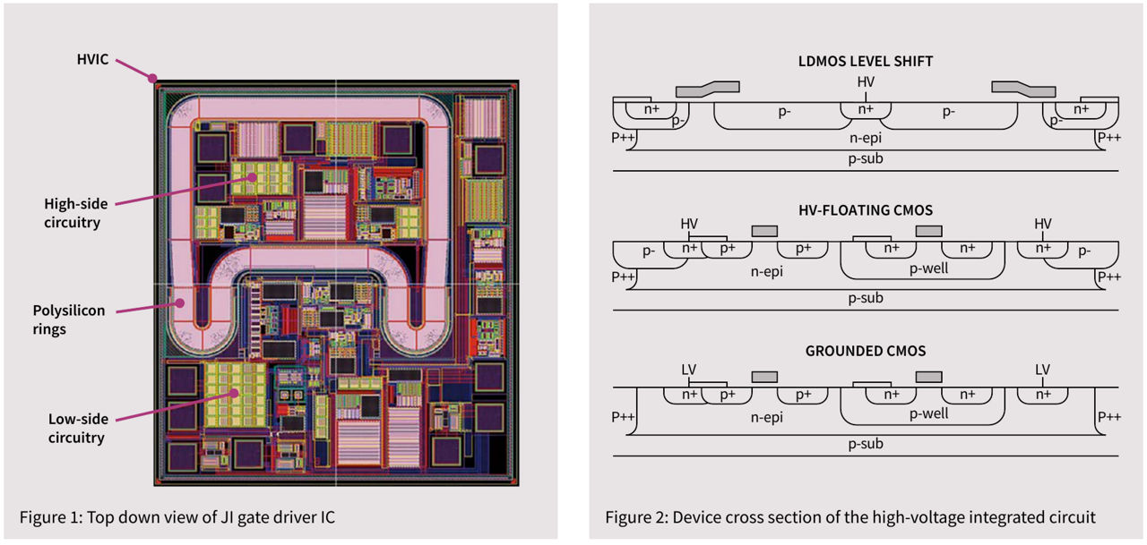
Top view of a JI gate driver IC (left) and cross-section of the high-voltage integrated circuit (right).
Next step:
Explore JI level-shift high-voltage gate driver ICs for IGBTs and MOSFETs.
A non-isolated driver shares an electrical reference with its input logic and the switch source or emitter. It is well suited to ground-referenced low-side drive or systems where isolation is provided elsewhere. TDI variants respond to the difference between two input pins, improving tolerance to local reference movement within the specified common-mode range.
Infineon non-isolated drivers are monolithic ground-referenced drivers built on the rugged HVIC process or a 130 nm process. The portfolio includes single- and dual-channel low-side drivers with options for output current, logic configuration and UVLO, in DSO-8 and small SOT23, WSON and TSNP packages, and families with overcurrent protection and fault reporting, for example 1ED4417x with ±5% OCP threshold tolerance. Truly differential input (TDI) drivers such as 1EDN-TDI tolerate ground shifts of ±70 V DC and ±150 V AC, which prevents false triggering of power MOSFETs. These drivers are used in power supplies, home appliances, BLDC motor drives, industrial automation and other applications where galvanic isolation is not required.
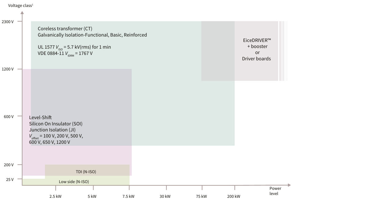
Voltage class and typical power level covered by each EiceDRIVER™ technology.
Values are typical or maximum values of selected product families. Always check the current datasheet.
- If galvanic isolation is mandatory, evaluate CT isolated drivers and the isolated bias-supply architecture.
- If no galvanic barrier is needed but the switch is floating, evaluate SOI or JI level-shift solutions.
- If the switch is ground-referenced, evaluate N-ISO or TDI devices.
- Then refine the choice using voltage class, channel count, source/sink current, delay, CMTI, UVLO, package, qualification, and required features.
Next step:
Apply isolation type filter to find products from the correct technology.
Next step:
Review full-bridge transformer drivers for isolated gate-driver bias supplies.
Share in WeChat
Scan the QR code with your WeChat App to share this page.
What are the main EiceDRIVER™ Gate Driver technologies?
The portfolio is organized around Coreless Transformer isolated technology, Silicon-on-Insulator level-shift technology, Junction Isolation level-shift technology, and non-isolated ground-referenced technology.
Is SOI galvanically isolated?
No. SOI electrically isolates active devices within the IC and supports high-voltage level shifting, but it does not create a galvanic safety barrier between the input and output domains.
What is the difference between SOI and JI?
Both can implement monolithic high-voltage level shifting. SOI isolates active devices with an insulating layer, while JI uses semiconductor junctions. Their transient behavior, losses, integration options, ratings, and product positioning can differ by device.
When should I choose an Isolated Gate Driver?
Choose an isolated Coreless Transformer driver when the system architecture, safety standard, working voltage, grounding scheme, noise environment, or transient environment requires galvanic separation.
What is CMTI and which technology needs it?
CMTI is immunity to fast common-mode voltage transients. It is a key parameter for isolated and level-shift drivers operating with fast switch-node edges.
What does non-isolated mean?
The input and output share an electrical reference; there is no galvanic barrier inside the driver.
Does non-isolated mean low voltage only?
No. It means the input and output share a reference. The applicable supply and bus-voltage limits depend on the specific architecture and device.
What is a truly differential input (TDI)?
A truly differential input responds to the voltage difference between two input pins and can improve tolerance to ground bounce or local reference movement within its specified range.
Can SOI or JI drive a high-side switch?
Yes. Both technologies are used in level-shift gate drivers that control floating high-side switches, typically with a bootstrap or another floating supply.
What is an HVIC Gate Driver?
A high-voltage integrated circuit (HVIC) gate driver combines high-voltage level-shifting circuits and low-voltage analog and digital circuits on one monolithic chip. Infineon JI drivers use HVIC technology with breakdown voltages above 700 V and 1400 V for 600 V and 1200 V operating offsets.
What do the IR and IRS prefixes mean?
IR denotes Gen 2 high-voltage driver ICs based on the original HVIC process; IRS denotes Gen 5, cost-effective pin-to-pin versions of Gen 2.
Why does negative VS transient immunity matter?
In inverters with high load current, parasitic inductance makes the switch-node (VS) voltage swing below the negative DC bus. If this exceeds the driver’s limits, the high-side output can flip or the IC can latch up. Infineon SOI drivers withstand −100 V for 300 ns.