
- ASIC
- Battery management ICs
- Clocks and timing solutions
- ESD and surge protection devices
- Automotive Ethernet
- Evaluation Boards
- High reliability
- Isolation
- Memories
- Microcontroller
- Power
- RF
- Security and smart card solutions
- Sensor technology
- Small signal transistors and diodes
- Transceivers
- Universal Serial Bus (USB)
- Wireless connectivity
- Search Tools
- Technology
- Packages
- Product Information
- Ordering
- Overview
- Automotive Ethernet PHY for in-vehicle networking
- Automotive Ethernet Switches for in-vehicle networking
- Overview
- Embedded flash IP solutions
- Flash+RAM MCP solutions
- F-RAM (Ferroelectric RAM)
- NOR flash
- nvSRAM (non-volatile SRAM)
- PSRAM – Pseudostatic RAM
- Radiation hardened and high-reliability memories
- SRAMs (Static Random Access Memory)
- Wafer and die memory solutions
- Overview
- AURIX™ TriCore™ MCUs
- PSOC™ MCUs
- TRAVEO™ T2G MCUs
- XMC™ MCUs
- Legacy MCUs
- MOTIX™ motor control SoCs/SIPs
- Overview
- AC-DC power conversion
- Automotive conventional powertrain ICs
- Class D audio amplifier ICs
- Contactless power and sensing ICs
- DC-DC converters
- Diodes and thyristors (Si/SiC)
- eFuses
- Gallium nitride (GaN)
- Gate Driver ICs
- IGBTs – Insulated gate bipolar transistors
- Intelligent power modules (IPM)
- JFETs
- LED driver ICs
- Motor drivers
- MOSFETs
- Power modules
- Power supply ICs
- Protection and monitoring ICs
- Silicon carbide (SiC)
- Smart power switches
- Solid state relays and isolators
- Wireless charging ICs
- Overview
- Antenna cross switches
- Antenna tuners
- Bias and control
- Coupler
- Driver amplifiers
- Rad hard microwave and RF
- Low noise amplifiers (LNAs)
- RF diode
- RF switches
- RF transistors
- Wireless control receiver
- Overview
- Calypso® products
- CIPURSE™ products
- Contactless memories
- OPTIGA™ embedded security solutions
- SECORA™ security solutions
- Security controllers
- Smart card modules
- Smart solutions for government ID
- Overview
- ToF 3D image sensors
- Current sensors
- Gas sensors
- Inductive position sensors
- MEMS microphones
- Pressure sensors
- Radar sensors
- Magnetic position sensors
- Magnetic speed sensors
- Capacitive sensors
- Temperature sensors
- Battery sensors
- Digital X-ray
- Computed tomography
- Sensor interface ASICs
- Overview
- Bipolar transistors
- Diodes
- Small signal/small power MOSFET
- Overview
- Automotive transceivers
- Control communication
- Powerline communications
- Overview
- USB 2.0 peripheral controllers
- USB 3.2 peripheral controllers
- USB hub controllers
- USB PD high-voltage microcontrollers
- USB-C AC-DC and DC-DC charging solutions
- USB-C charging port controllers
- USB-C Power Delivery controllers
- Overview
- AIROC™ Automotive wireless
- AIROC™ Bluetooth® and multiprotocol
- AIROC™ connected MCU
- AIROC™ Wi-Fi + Bluetooth® combos
- AIROC™ Ultra-Wide Band Solutions
- Overview
- Commercial off-the-shelf (COTs) memory portfolio
- Defense memory portfolio
- High-reliability power conversion and management
- Overview
- Rad hard microwave and RF
- Radiation hardened power
- Space memory portfolio
- Overview
- Parallel NOR flash
- SEMPER™ NOR flash family
- SEMPER™ X1 LPDDR flash
- Serial NOR flash
- Overview
-
32-bit TriCore™ AURIX™ – TC2x
- Overview
- AURIX™ family – TC21xL
- AURIX™ family – TC21xSC (wireless charging)
- AURIX™ family – TC22xL
- AURIX™ family – TC23xL
- AURIX™ family – TC23xLA (ADAS)
- AURIX™ family – TC23xLX
- AURIX™ family – TC264DA (ADAS)
- AURIX™ family – TC26xD
- AURIX™ family – TC27xT
- AURIX™ family – TC297TA (ADAS)
- AURIX™ family – TC29xT
- AURIX™ family – TC29xTT (ADAS)
- AURIX™ family – TC29xTX
- AURIX™ TC2x emulation devices
-
32-bit TriCore™ AURIX™ – TC3x
- Overview
- AURIX™ family - TC32xLP
- AURIX™ family – TC33xDA
- AURIX™ family - TC33xLP
- AURIX™ family – TC35xTA (ADAS)
- AURIX™ family – TC36xDP
- AURIX™ family – TC37xTP
- AURIX™ family – TC37xTX
- AURIX™ family – TC38xQP
- AURIX™ family – TC39xXA (ADAS)
- AURIX™ family - TC39xXX/XP
- AURIX™ family – TC3Ex
- AURIX™ TC37xTE (emulation devices)
- AURIX™ TC39xXE (emulation devices)
- 32-bit TriCore™ AURIX™ – TC4x
- Overview
- PSOC™ 4 Microcontroller: Arm® Cortex®-M0/M0+
- PSOC™ 4 HV Arm® Cortex®-M0+
- PSOC™ 5 LP Arm® Cortex®-M3
- PSOC™ 6 Arm® Cortex®-M4/M0+
- PSOC™ Multitouch Touchscreen Controller
- PSOC™ Control C3 Arm® Cortex®-M33
- PSOC™ Automotive 4: Arm® Cortex®-M0/M0+
- PSOC™ Edge Arm® Cortex® M55/M33
- PSOC™ Control C1 Arm® Cortex®-M0
- Overview
- 32-bit TRAVEO™ T2G Arm® Cortex® for body
- 32-bit TRAVEO™ T2G Arm® Cortex® for cluster
- Overview
- 32-bit XMC1000 industrial microcontroller Arm® Cortex®-M0
- 32-bit XMC4000 industrial microcontroller Arm® Cortex®-M4
- XMC5000 Industrial Microcontroller Arm® Cortex®-M4F
- 32-bit XMC7000 Industrial Microcontroller Arm® Cortex®-M7
- Overview
- Legacy 32-bit MCU
- Legacy 8-bit/16-bit microcontroller
- Other legacy MCUs
- 32-bit FM Arm® Cortex® Microcontroller
- Sensing controllers
- Overview
- AC-DC integrated power stage - CoolSET™
- AC-DC PWM and PFC controller
- Overview
- Bridge rectifiers & AC switches
- CoolSiC™ Schottky diodes
- Diode bare dies
- Silicon diodes
- Thyristor / Diode Power Modules
- Thyristor soft starter modules
- Thyristor/diode discs
- Overview
- GaN bidirectional switches
- GaN smart
- GaN transistors (GaN HEMTs)
- GaN with integrated driver
- GaN bare dies
- Overview
- Automotive gate driver ICs
- Gate Driver ICs for GaN HEMTs
- Gate Driver ICs for SiC MOSFETs
- Half-Bridge Gate Driver ICs
- High-Side Gate Driver ICs
- Isolated Gate Driver ICs
- Level-Shift Gate Driver ICs
- Low-Side Gate Driver ICs
- Three-Phase Gate Driver ICs
- Transformer Driver ICs
- Overview
- AC-DC LED driver ICs
- Ballast IC
- DC-DC LED driver IC
- LED dimming interface IC
- Linear LED driver IC
- LITIX™ - Automotive LED Driver IC
- NFC wireless configuration IC with PWM output
- VCSEL driver
- Overview
- BLDC motor drivers
- BDC motor drivers
- Stepper & servo motor drivers
- Motor drivers with MCU
- Bridge drivers with MOSFETs
- Gate Driver ICs
- Overview
- Automotive MOSFET: 30 V to 800 V
- Dual MOSFETs
- MOSFET (Si & SiC) Modules
- N-channel depletion mode MOSFET
- N-channel MOSFETs
- P-channel MOSFETs
-
Silicon carbide CoolSiC™ MOSFETs
- Overview
- Silicon Carbide MOSFET modules
- Silicon carbide MOSFET discretes
- Silicon carbide MOSFETs bare dies
- Silicon Carbide Bidirectional Switches
- 400 V / 440 V Silicon Carbide MOSFETs
- 650 V Silicon Carbide MOSFETs
- 750 V Silicon Carbide MOSFETs
- 1200 V Silicon Carbide MOSFETs
- 1700 V Silicon Carbide MOSFETs
- 2000 V Silicon Carbide MOSFETs
- 2300 V Silicon Carbide MOSFETs
- 3300 V Silicon Carbide MOSFETs
- Small signal/small power MOSFET
- Overview
- IGBT modules
- MOSFET (Si & SiC) Modules
- Intelligent power modules (IPM)
- Diodes and thyristors (Si/SiC)
- Automotive IGBT and CoolSiC™ MOSFET modules
- High density power modules
- Overview
- Automotive transceivers
- Linear voltage regulators
- Power management ICs (PMIC)
- Automotive switching regulators
- System Basis Chips (SBC)
- Overview
- High-side switches
- Low-side switches
- Multichannel SPI Switches & Controller
- Automotive eFuses
- Overview
- Radar sensors for automotive
- Radar sensors for IoT
- Overview
- EZ-USB™ CX3 MIPI CSI2 to USB 3.0 camera controller
- EZ-USB™ FX10 & FX5N USB 10Gbps peripheral controller
- EZ-USB™ FX20 USB 20 Gbps peripheral controller
- EZ-USB™ FX3 USB 5 Gbps peripheral controller
- EZ-USB™ FX3S USB 5 Gbps peripheral controller with storage interface
- EZ-USB™ FX5 USB 5 Gbps peripheral controller
- EZ-USB™ SD3 USB 5 Gbps storage controller
- EZ-USB™ SX3 FIFO to USB 5 Gbps peripheral controller
- Overview
- EZ-PD™ PMG1-B1 Battery Charge Controller with USB-C PD MCU
- EZ-PD™ PMG1-S0 high-voltage MCU with USB-C and PD
- EZ-PD™ PMG1-S1 high-voltage MCU with USB-C and PD
- EZ-PD™ PMG1-S2 high-voltage MCU with USB PD
- EZ-PD™ PMG1-S3 high-voltage MCU with USB-C & PD
- EZ-PD™ PMG1-B2 Battery Charge Controller with USB-C PD MCU
- Overview
- EZ-PD™ CCG3 USB type-C port controller PD
- EZ-PD™ CCG3PA USB-C and PD
- EZ-PD™ CCG3PA-NFET USB-C PD controller
- EZ-PD™ CCG7x consumer USB-C Power Delivery & DC-DC controller
- EZ-PD™ PAG1: power adapter generation 1
- EZ-PD™ PAG2: Power Adapter Generation 2
- EZ-PD™ PAG2-PD USB-C PD Controller
- Overview
- EZ-PD™ ACG1F one-port USB-C controller
- EZ-PD™ CCG2 USB Type-C port controller
- EZ-PD™ CCG3PA Automotive USB-C and Power Delivery controller
- EZ-PD™ CCG4 two-port USB-C and PD
- EZ-PD™ CCG5 dual-port and CCG5C single-port USB-C PD controllers
- EZ-PD™ CCG6 one-port USB-C & PD controller
- EZ-PD™ CCG6_CFP and EZ-PD™ CCG8_CFP Dual-Single-Port USB-C PD
- EZ-PD™ CCG6DF dual-port and CCG6SF single-port USB-C PD controllers
- EZ-PD™ CCG7D Automotive dual-port USB-C PD + DC-DC controller
- EZ-PD™ CCG7S Automotive single-port USB-C PD solution with a DC-DC controller + FETs
- EZ-PD™ CCG8 dual-single-port USB-C PD
- EZ-PD™ CMG1 USB-C EMCA controller
- EZ-PD™ CMG2 USB-C EMCA controller with EPR
Browse by core architecture
Browse by key technologies
Browse by design resources & partners
- LATEST IN
- Aerospace and defense
- AI and data center
- Automotive
- Communications
- Consumer electronics
- Industrial
- Security solutions
- Smart home and building
- Solutions
- Overview
- Defense applications
- Space applications
- Overview
- Data center power solutions
- Edge computing
- Machine Learning Edge AI
- Overview
- ADAS & autonomous driving
- Automotive body electronics
- Automotive LED lighting systems
- Automotive zonal architecture
- Chassis control & safety
- Electric vehicle drivetrain system
- EV thermal management system
- In-vehicle infotainment & HMI
- Light electric vehicle solutions
- Overview
- Satellite communications
- Telecommunications infrastructure
- Overview
- AR and smart glasses
- Complete system solutions for smart TVs
- Consumer Wearables
- Drones
- Home appliances
- Mobile device and smartphone solutions
- Photovoltaic
- Power adapters and chargers
- Semiconductor solutions for home entertainment applications
- Smart conference systems
- Overview
- Asset Tracking
- Battery energy storage (BESS)
- Battery formation and testing
- Digital health
- Electric forklifts
- EV charging
- High voltage solid-state power distribution
- Hydrogen electrolysis
- Industrial & Medical SMPS
- Industrial automation
- Industrial motor drives and controls
- Industrial robots
- LED lighting system design
- Light electric vehicle solutions
- Photovoltaic
- Power adapters and chargers
- Power tools
- Power transmission and distribution
- Robotics
- Traction
- Uninterruptible power supplies (UPS)
- Wind power
- Overview
- Access control and ticketing
- Device authentication and brand protection
- Embedded security for the Internet of Things (IoT)
- eSIM applications
- Government identification
- Mobile security
- Payment solutions
- Overview
- Domestic robots
- Heating ventilation and air conditioning (HVAC)
- Home and building automation
- PC accessories
- Semiconductor solutions for home entertainment applications
- Overview
- Battery management systems (BMS)
- Connectivity
- Human Machine Interface
- Machine Learning Edge AI
- Motor control
- Power conversion
- Security
- Sensor solutions
- System diagnostics and analytics
- Overview
- Data center power distribution
- FPGAs in datacenter applications
- Power system reliability modeling
-
Server rack power management
- Overview
- AI accelerator cards
- AMD CPU voltage regulator Ics
- Ampere CPU voltage regulator ICs
- Intel CPU voltage regulator Ics
- Intermediate Bus Converter (IBC)
- Network switches for AI data centers and server racks
- Server battery backup units (BBU)
- Server power path protection
- Server power supply units (PSU)
- SmartNIC cards
- Overview
- Automotive animated LED lighting system
- Automotive LED front single light functions
- Automotive LED rear single light functions
- Full LED headlight system - multi-channel LED driver
- LED driver solutions for electric two- and three-wheelers
- LED pixel light controller - supply & communication
- Static interior ambient LED light
- Overview
- Active suspension control
- Automotive braking solutions
- Automotive steering solutions
- Chassis domain control
- Overview
-
Automotive battery management system
- Overview
- Automotive battery cell monitoring & balancing
- Automotive battery control unit (BCU)
- Automotive battery isolated communication
- Automotive battery management system (BMS) - 12 V to 24 V
- Automotive battery management system (BMS) - 48 V
- Automotive battery management system (BMS) - high-voltage
- Automotive battery pack monitoring
- Automotive battery passport & event logging
- Automotive battery protection & disconnection
- Automotive current sensing & coulomb counting
- BMS (electric two- & three-wheelers)
- Auxiliary inverter
- Auxiliary inverter - high-voltage (commercial vehicles)
- DC-DC converter high-voltage
- DC-DC converter high-voltage (commercial vehicles)
- EV charging
- EV traction inverter
- FCEV powertrain solutions
- On-board charging (electric commercial vehicles)
- On-board charging (OBC)
- On-board charging (OBC) solutions for electric two- and three-wheelers
- Traction inverter (electric commercial vehicles)
- Traction inverter (electric two- & three-wheelers)
- Overview
- Audio amplifier solutions
- Complete system solutions for smart TVs
- Distribution audio amplifier unit solutions
- Home theater installation speaker system solutions
- Party speaker solutions
- PoE audio amplifier unit solutions
- Portable speaker solutions
- Powered active speaker systems
- Remote control
- Smart speaker designs
- Soundbar solutions
- Overview
- Disposable healthcare equipment
- Durable healthcare equipment
- Healthcare wearables
- Overview
- Data center power solutions
- Digital input/output (I/O) modules
- DIN rail power supply solutions
- Home and building automation
- Industrial HMI Monitors and Panels
- Industrial motor drives and controls
- Industrial PC
- Industrial robots
- Machine vision
- Mobile robots (AGV, AMR)
- Programmable logic controller (PLC)
- Solid-state circuit breaker (SSCB)
- Uninterruptible power supplies (UPS)
- Overview
- Automotive battery management system
- Industrial and consumer BMS
- Overview
- AC-DC power conversion
- DC-DC power conversion
- Overview
- Power supply health monitoring
- LATEST IN
- Digital documentation
- Boards & Kits
- Finder & selection tools
- Platforms
- Services
- Simulation & Modeling
- Software
- Tools
- Partners
- Infineon for Makers
- University Alliance Program
- Overview
- Bipolar Discs Finder
- Bipolar Module Finder
- Connected Secure Systems Finder
- Diode Rectifier Finder
- ESD Protection Finder
- Evaluation Board Finder
- Gate Driver Finder
- IGBT Discrete Finder
- IGBT Module Finder
- IPM Finder
- Microcontroller Finder
- MOSFET Finder
- PMIC Finder
- Product Finder
- PSOC™ and FMx MCU Board & Kit Finder
- Radar Finder
- Reference Design Finder
- Simulation Model Finder
- Smart Power Switch Finder
- Transceiver Finder
- Voltage Regulator Finder
- Wireless Connectivity Board & Kit Finder
- Infineon Gate Driver Recommendation Tool
- Overview
- AIROC™ software & tools
- AURIX™ software & tools
- DRIVECORE™ for automotive software development
- iMOTION™ software & tools
- Infineon Smart Power Switches & Gate Driver Tool Suite
- MOTIX™ software & tools
- OPTIGA™ software & tools
- PSOC™ software & tools
- TRAVEO™ software & tools
- XENSIV™ software & tools
- XMC™ software & tools
- Overview
- HiRel Fit Rate Tool
- Infineon Designer
- Interactive product sheet
- IPOSIM Online Power Simulation Platform
- InfineonSpice Offline Simulation Tool
- OPTIREG™ automotive power supply ICs Simulation Tool (PLECS)
- Power MOSFET Simulation Models
- PowerEsim Switch Mode Power Supply Design Tool
- Solution Finder
- XENSIV™ Magnetic Sensor Simulation Tool
- Overview
- Configuration
- Hardware Development
- Programming & Testing
- SDK
- Tools Archive
- Utilities
- Overview
- AURIX™ certifications
- AURIX™ development tools
-
AURIX™ Embedded Software
- Overview
- AURIX™ Applications software
- AURIX™ Artificial Intelligence
- AURIX™ Gateway
- AURIX™ iLLD Drivers
- Infineon safety
- AURIX™ Security
- AURIX™ TC3xx Motor Control Application Kit
- AURIX™ TC4x SW application architecture
- Infineon AUTOSAR
- Communication and Connectivity
- Middleware
- Non AUTOSAR OS/RTOS
- OTA
- AURIX™ Microcontroller Kits
- Overview
- TRAVEO™ Development Tools
- TRAVEO™ Embedded Software
- Overview
- XENSIV™ Development Tools
- XENSIV™ Embedded Software
- XENSIV™ evaluation boards
- Overview
- CAPSENSE™ Controllers Code Examples
- Memories for Embedded Systems Code Examples
- PSOC™ 1 Code Examples for PSOC™ Designer
- PSOC™ 3 Code Examples for PSOC™ Creator
- PSOC™ 3/4/5 Code Examples
- PSOC™ 4 Code Examples for PSOC™ Creator
- PSOC™ 6 Code Examples for PSOC™ Creator
- PSOC™ 63 Code Examples
- USB Controllers Code Examples
- Overview
- AIROC™ Wi-Fi & Bluetooth EZ-Serial Module Firmware Platform
- AIROC™ Wi-Fi & Bluetooth Linux and Android Drivers
- emWin Graphics Library and GUI for PSOC™
- Infineon Complex Device Driver for Battery Management Systems
- Memory Solutions Hub
- PSOC™ 6 Peripheral Driver Library (PDL) for PSOC™ Creator
- USB Controllers EZ-USB™ GX3 Software and Drivers
- Overview
- CAPSENSE™ Controllers Configuration Tools EZ-Click
- DC-DC Integrated POL Voltage Regulators Configuration Tool – PowIRCenter
- EZ-USB™ SX3 Configuration Utility
- FM+ Configuration Tools
- FMx Configuration Tools
- Tranceiver IC Configuration Tool
- USB EZ-PD™ Configuration Utility
- USB EZ-PD™ Dock Configuration Utility
- USB EZ-USB™ HX3C Blaster Plus Configuration Utility
- USB UART Config Utility
- XENSIV™ Tire Pressure Sensor Programming
- Overview
- EZ-PD™ CCGx Dock Software Development Kit
-
FMx Softune IDE
- Overview
- RealOS™ Real-Time Operating System
- Softune IDE Language tools
- Softune Workbench
- Tool Lineup for F2MC-16 Family SOFTUNE V3
- Tool Lineup for F2MC-8FX Family SOFTUNE V3
- Tool Lineup for FR Family SOFTUNE V6
- Virtual Starter Kit
- Windows 10 operation of released SOFTUNE product
- Windows 7 operation of released SOFTUNE product
- Windows 8 operation of released SOFTUNE product
- Infineon GUI Designer
- ModusToolbox™ Software
- PSOC™ Creator Software
- Radar Development Kit
- RUST
- USB Controllers SDK
- Wireless Connectivity Bluetooth Mesh Helper Applications
- XMC™ DAVE™ Software
- Overview
- AIROC™ Bluetooth® Connect App Archive
- Cypress™ Programmer Archive
- EZ-PD™ CCGx Power Software Development Kit Archive
- ModusToolbox™ Software Archive
- PSOC™ Creator Archive
- PSOC™ Designer Archive
- PSOC™ Programmer Archive
- USB EZ-PD™ Configuration Utility Archives
- USB EZ-PD™ Host SDK Archives
- USB EZ-USB™ FX3 Archive
- USB EZ-USB™ HX3PD Configuration Utility Archive
- WICED™ Smart SDK Archive
- WICED™ Studio Archive
- Overview
- Infineon Developer Center Launcher
- Infineon Register Viewer
- Pin and Code Wizard
- Timing Solutions
- Wireless Connectivity
- LATEST IN
- Support
- Training
- Developer Community
- News
Business & Financial Press
Oct 15, 2026
Business & Financial Press
Oct 14, 2026
Business & Financial Press
Oct 07, 2026
Business & Financial Press
Oct 05, 2026
- Company
- Our stories
- Events
- Press
- Investor
- Careers
- Quality
- Latest news
Business & Financial Press
Oct 15, 2026
Business & Financial Press
Oct 14, 2026
Business & Financial Press
Oct 07, 2026
Business & Financial Press
Oct 05, 2026
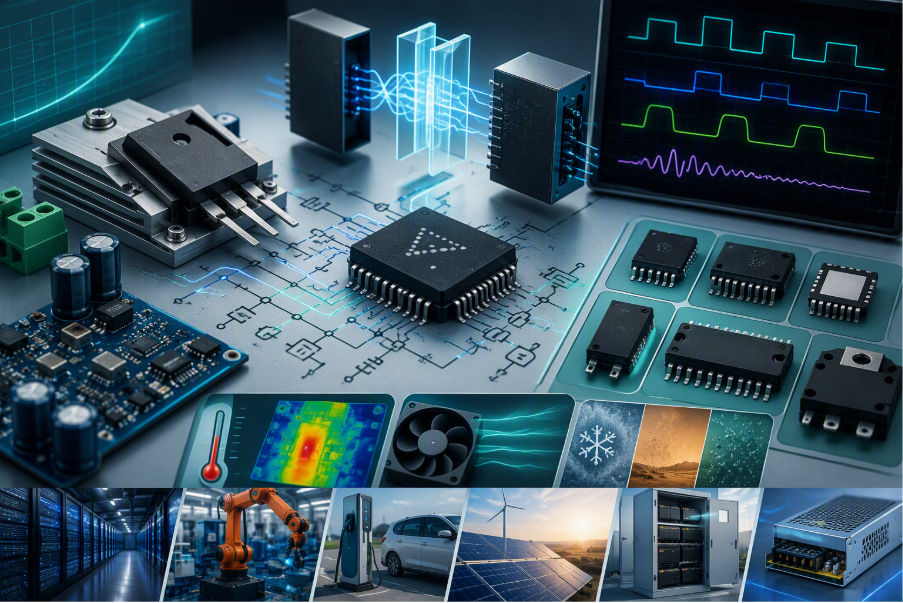
A Gate Driver parameter is a measurable electrical, timing, isolation, mechanical, thermal, interface, robustness, or qualification specification used to determine whether a driver fits a power-switch application. Parameters describe both the operating envelope and the behavior of the device under defined test conditions.
Typical examples include peak source and sink current, pull-up and pull-down resistance, supply-voltage range, undervoltage-lockout thresholds, propagation delay, channel-to-channel skew, minimum pulse width, common-mode transient immunity, isolation working voltage, creepage, clearance, junction-temperature range, and package type.
A parameter is useful only when its definition and test conditions are understood. Two devices can quote the same headline value while differing in load, supply, temperature, pulse duration, measurement threshold, polarity, or failure criterion. Final comparison therefore requires the current datasheet, the selected switch datasheet, and worst-case system conditions.
A feature is a function the device provides. A parameter quantifies how that function behaves. Keeping the distinction clear prevents a feature checklist from replacing engineering comparison. Examples of feature-parameters pairs are listed in the table below.
Explore EiceDRIVER™ Gate Driver ICs →
Review the portfolio by topology, switch technology, isolation and application.
- 1. Define the power switch and operating points. Identify IGBT, Si MOSFET, SiC MOSFET, or GaN HEMT; bus voltage; switching frequency; duty cycle; gate-charge curve; gate-voltage limits; and short-circuit behavior.
- 2. Lock the topology and channel architecture. Determine low-side, high-side, half-bridge, full-bridge, three-phase, dual-floating, isolated single/dual, or other configuration. Establish each output reference and the required channel independence.
- 3. Set the gate-bias and drive-strength target. Define positive and negative gate-bias rails, estimate source/sink current, and evaluate output resistance, external gate resistance, reverse current, pulse conditions, driver loss, EMI and overshoot.
- 4. Choose voltage class and isolation concept. Apply margin for the DC bus, ringing and transients. If galvanic isolation is required, select the insulation class from the applicable system standard and verify all barrier and spacing ratings.
- 5. Check timing and usable PWM range. Review propagation delay, delay matching, rise/fall behavior, minimum pulse width, pulse-width distortion, input filtering, deadtime and startup or recovery timing.
- 6. Check transient and interface robustness. Verify CMTI, negative switch-node tolerance, logic-operational limits, UVLO behavior, input thresholds, hysteresis, default state, and 3.3 V or 5 V compatibility.
- 7. Select package, thermal range and qualification. Confirm package, pinout, creepage, clearance, isolation capacitance, thermal resistance, power dissipation, temperature range, MSL, ESD, industrial or automotive qualification, certification and safety support.
- 8. Add protection, control and diagnostic features. After the electrical envelope is fixed, select DESAT/OCP, Miller clamp, soft-off, two-level turn-off, sensing, bootstrap, slew-rate control, fault signaling or digital configuration as needed.
- 9. Shortlist and validate. Use the parametric table or recommendation tool, then verify current datasheets, models, layout, startup, switching, fault response, EMI, thermal behavior and worst-case hardware performance.
Explore the Gate Driver Product Table →
Filter by key selection parameters, then validate shortlisted devices against current datasheets.
Start with the switch datasheet. Record recommended turn-on and turn-off gate voltages, absolute gate limits, total and Miller gate charge (Qg and Qgd), threshold range, internal gate resistance and short-circuit behavior. IGBTs, Si MOSFETs, SiC MOSFETs and GaN HEMTs can require different bias and protection schemes.
- Switch technology
Identify IGBT, silicon MOSFET, SiC MOSFET or GaN HEMT; each has a different gate-drive envelope. - Gate-voltage limits
Keep gate bias, ringing and transients within the switch’s absolute maximum ratings. - Turn-on and turn-off gate bias
Compare the switch’s recommended VGS/VGE values and allowable negative bias with the driver’s output supply. - Threshold and gate resistance
Check threshold spread, internal resistance and recommended external gate resistance when setting noise margin and speed. - Gate charge and Miller charge
Use Qg and Qgd at relevant operating conditions to estimate drive current and switching behavior. - Short-circuit behavior
Use the switch’s fault withstand and turn-off guidance to set protection and shutdown requirements.
Topology sets the number and reference of driver outputs. A low-side switch may need one ground-referenced output; a half-bridge needs high- and low-side drive; a full bridge typically needs four outputs and a three-phase inverter six. Check channel independence, shared supplies, fault handling, interlock and floating or isolated references.
- Topology and output reference
Choose low-side, floating high-side, half-bridge, full-bridge, three-phase or isolated drive as the circuit requires. - Channel count and independence
Count the outputs and check whether their supplies, grounds, enable and fault functions are shared. - Input and output polarity
Check inverting/non-inverting behavior and the state of each output when inputs or enable are inactive. - Interlock and shoot-through prevention
Where provided, check how the driver prevents simultaneous conduction and how this affects control timing.
Source current charges the gate; sink current discharges it. Compare peak-current definitions, source and sink separately, pull-up/pull-down resistance, external gate resistance, pulse duration and thermal dissipation. I ≈ Qg/t is only an initial average-current estimate: verify current at the Miller plateau, losses, overshoot and EMI.
- Peak source current
Check the current available to charge the gate, including the specified output voltage and pulse test condition. - Peak sink current
Check turn-off current separately; the pull-down path may have a different rating from the pull-up path. - Pull-up and pull-down resistance
Compare output resistance over supply and temperature to estimate current at the Miller plateau. - Output structure and external booster
Check separate source/sink outputs, external gate-network options and whether a booster is needed. - Reverse current and output clamping
Check current flowing back into the output and any clamping or active-shutdown behavior during transients. - Output-stage dissipation
Verify switching-related driver loss and temperature, not just a headline peak-current value.
Voltage class relates to supported switch-node offset or domain voltage, with the exact definition depending on driver configuration. It is not gate-drive supply voltage or isolation voltage. Check bus and transient margin, VCC/VDD/VEE/VB/VBS operating and absolute-maximum ranges, positive/negative bias, quiescent current and bootstrap refresh or startup needs.
- Driver voltage class
Check the datasheet definition of the supported switch-node offset, domain or supply class for the chosen architecture. - Input- and output-side supply ranges
Compare VCC, VDD, VEE, VB and VBS operating ranges with the required positive and negative gate bias. - Operating versus absolute maximum ratings
Use the operating range for normal design; absolute maximum values are not continuous operating targets. - Quiescent and startup current
Size bias supplies for steady-state demand and startup behavior. - Bootstrap diode or switch
Check charging resistance, reverse behavior, capacitor requirements and overcharge control where integrated. - Charge pump and refresh
Check startup, high-side on-time and duty-cycle limits for the actual supply architecture.
Choose non-isolated, functional, basic or reinforced isolation according to the system insulation concept and applicable standard. Verify working, repetitive peak, transient, surge and test voltages, barrier lifetime, creepage, clearance, material group, pollution degree, altitude and device/package certification. A test-voltage figure alone is insufficient.
- Isolation class
Select functional, basic or reinforced insulation from the applicable system standard and insulation concept. - Working and repetitive peak voltage
Check the applicable continuous and repetitive barrier ratings, not only a test-voltage headline. - Transient, surge and dielectric test voltage
Check each rating against its stated test conditions and the system’s overvoltage requirements. - Barrier lifetime and capacitance
Review lifetime assumptions and coupling across the barrier when assessing insulation and common-mode current. - Creepage and clearance
Verify package spacing together with material group, pollution degree, altitude and PCB implementation. - Certification
Confirm the exact device, package and certificate rather than assuming a family-wide approval.
Explore Isolated Gate Drivers → Review isolation and package options.
Compare turn-on/off propagation delay under defined test conditions and determine whether matching means channel-to-channel, edge-to-edge or part-to-part variation. Minimum pulse width is the shortest reliably transferred input pulse; pulse-width distortion is the input-to-output pulse-duration difference. Include both in narrow-PWM and deadtime analysis alongside filtering, rise/fall and recovery times.
- Turn-on and turn-off propagation delay
Compare input-to-output delay at the stated supply, load, temperature and measurement thresholds. - Delay matching and skew
Determine whether the rating covers channels, edges, complementary outputs or different devices. - Output rise and fall time
Read the specified load and test setup; driver output transition time is not the power-switch transition time. - Minimum pulse width
Check the shortest input pulse that is reliably transferred to the output. - Pulse-width distortion
Check the difference between input and output pulse duration, especially at narrow PWM duty cycles. - Deadtime range and tolerance
Where integrated, check programmed or fixed deadtime together with worst-case delay variation. - Enable, startup and recovery timing
Check enable/disable, UVLO recovery and fault-reset delays before defining restart behavior.
CMTI describes immunity to common-mode voltage slew under specified polarity, voltage, output state and failure criteria. Compare those conditions with the application’s worst-case slew rate. For level-shift drivers also check negative switch-node depth/duration, logic-operational range, reverse current and recovery. Layout and parasitic coupling remain important.
- Common-mode transient immunity (CMTI)
Compare the specified slew-rate immunity, polarity, voltage, output state and failure criterion. - Negative switch-node tolerance
Check allowable negative VS/HS excursion, duration, operating limits and recovery. - Reverse current and ground shift
Review current paths and input-reference tolerance when fast switching moves local potentials. - ESD and transient robustness
Review specified HBM/CDM, latch-up and pin absolute maximum ratings for the exact device.
Check UVLO rising and falling thresholds, hysteresis, output state, channel independence and recovery time against gate-bias tolerances. Confirm input VIH/VIL, hysteresis, input current, polarity, default state, pin limits and 3.3 V or 5 V compatibility; differential inputs require common-mode and timing review.
- UVLO rising and falling thresholds
Check when the output enables and disables as the bias supply rises or falls. - UVLO hysteresis and output state
Check noise margin, channel independence and the defined output behavior during undervoltage. - Logic-high and logic-low thresholds
Compare VIH/VIL, input current and logic-supply range with the controller’s actual levels. - Input hysteresis and filtering
Check Schmitt-trigger or filter behavior against noise and minimum-pulse requirements. - Default and fail-safe state
Check internal pulls, input polarity, enable state and output behavior at startup or loss of control. - Differential input common-mode range
For differential or TDI interfaces, check permissible ground shift and timing limits.
Package affects board area, pinout, spacing, parasitics and manufacturability. Verify package creepage and clearance in the board design; junction/ambient temperature, thermal resistance, output-stage dissipation, exposed-pad requirements, moisture sensitivity and ESD performance at the intended operating conditions.
- Package, pinout and pitch
Compare body size, pin arrangement, exposed pad and layout or replacement constraints. - Creepage and clearance on the board
Verify the actual package-to-PCB spacing rather than relying on package dimensions alone. - Operating temperature
Check junction and ambient ranges for the intended industrial or automotive conditions. - Thermal resistance and power dissipation
Evaluate output-stage loss and junction temperature using the real PCB copper and ambient conditions. - Moisture sensitivity and assembly
Check MSL and manufacturing requirements for the selected package. - ESD, latch-up and absolute maximums
Review device robustness ratings alongside layout and handling requirements.
Verify AEC-Q100 status for the exact automotive part, and relevant industrial or isolation certificates for the specific product and package. Safety documentation can support a system safety concept, but component qualification does not itself establish an ASIL or SIL claim. Confirm assumptions, diagnostics, product status and system-level validation.
- Automotive or industrial qualification
Confirm the qualification and temperature grade of the exact orderable device; check AEC-Q100 where required. - Isolation approvals
Verify applicable UL, VDE or IEC documentation for the exact package and part. - Functional-safety documentation
Check availability and assumptions of safety manuals, failure-rate data and FMEDA support. - Protection thresholds and timing
If DESAT or OCP is selected, check threshold, blanking, filter, response and reset parameters. - Miller clamp and controlled turn-off
Where used, check clamp threshold/current, soft-off current and two-level turn-off level/time. - Slew-rate control
Where programmable, check available drive settings, resolution, timing and turn-on/turn-off independence. ~ - Sensing and diagnostic interface
Where integrated, check gain, offset, bandwidth, fault/ready timing, register and SPI/I²C behavior. - Product status and lifecycle
Check availability, change notifications and replacement needs for the chosen part.
Share in WeChat
Scan the QR code with your WeChat App to share this page.
What are the most important Gate Driver parameters?
Start with switch compatibility, topology, channel count, voltage class, source/sink current, output resistance, supply range, isolation, timing, CMTI, negative-transient behavior, UVLO, logic interface, package, thermal limits and qualification. The priority changes with the application.
How much gate-driver current do I need?
Use I ≈ Qg/t only as a first estimate. Then verify current around the Miller plateau, total pull-up and pull-down resistance, switching frequency, pulse conditions, driver dissipation, EMI, overshoot and the switch gate-charge curve at the intended operating point.
Is peak output current enough to compare drivers?
No. Compare the peak-current definition and test condition, output resistance, current at the relevant output voltage, pulse duration, source/sink asymmetry, reverse-current behavior, supply voltage and thermal performance.
What is the difference between voltage class, gate-drive supply and isolation voltage?
Voltage class describes the supported switch-node offset or application domain, with the exact definition depending on configuration. Gate-drive supply is the local voltage used by the output stage. Isolation ratings characterize the galvanic barrier. They answer different design questions.
What is propagation-delay matching?
It is a specified difference in delay between channels, edges or parts under defined conditions. Determine whether the datasheet specifies channel-to-channel, rise-to-fall, complementary-edge or part-to-part matching before using the value in a deadtime budget.
Why do minimum pulse width and pulse-width distortion matter?
Minimum pulse width determines whether a narrow PWM command is transferred reliably. Pulse-width distortion changes the duration of the output pulse relative to the input. Both can limit usable duty cycle at high switching frequency.
How high should CMTI be?
It should exceed the worst-case common-mode slew rate at the driver with suitable design margin. Compare test polarity, common-mode voltage, output state, static or dynamic method, PVT conditions and failure criterion.
How do I choose UVLO thresholds?
Choose rising and falling thresholds that keep the power switch safely off below its usable gate voltage while permitting normal operation across bias-supply tolerance and temperature. Also check hysteresis, output state and recovery timing.
Are DESAT and active Miller clamp parameters?
They are features. DESAT threshold, blanking, filter and response time are parameters. Miller-clamp threshold, current and activation behavior are parameters.
Why does channel count matter?
It determines topology fit and integration, but also affects output references, shared supplies, enable/fault grouping, timing coordination, package size and fault behavior.
Can I select a Gate Driver only from a parametric table?
No. A table is a shortlisting tool. Final selection requires the current driver and switch datasheets, safety requirements, simulation, layout review and hardware validation.
Does an automotive-qualified driver make the system functionally safe?
No. Component qualification and available safety documentation can support a system safety concept, but the system designer remains responsible for the final ASIL/SIL claim, diagnostics, assumptions and validation