
- ASIC
- Battery management ICs
- Clocks and timing solutions
- ESD and surge protection devices
- Automotive Ethernet
- Evaluation Boards
- High reliability
- Isolation
- Memories
- Microcontroller
- Power
- RF
- Security and smart card solutions
- Sensor technology
- Small signal transistors and diodes
- Transceivers
- Universal Serial Bus (USB)
- Wireless connectivity
- Search Tools
- Technology
- Packages
- Product Information
- Ordering
- Overview
- Automotive Ethernet PHY for in-vehicle networking
- Automotive Ethernet Switches for in-vehicle networking
- Overview
- Embedded flash IP solutions
- Flash+RAM MCP solutions
- F-RAM (Ferroelectric RAM)
- NOR flash
- nvSRAM (non-volatile SRAM)
- PSRAM – Pseudostatic RAM
- Radiation hardened and high-reliability memories
- SRAMs (Static Random Access Memory)
- Wafer and die memory solutions
- Overview
- AURIX™ TriCore™ MCUs
- PSOC™ MCUs
- TRAVEO™ T2G MCUs
- XMC™ MCUs
- Legacy MCUs
- MOTIX™ motor control SoCs/SIPs
- Overview
- AC-DC power conversion
- Automotive conventional powertrain ICs
- Class D audio amplifier ICs
- Contactless power and sensing ICs
- DC-DC converters
- Diodes and thyristors (Si/SiC)
- eFuses
- Gallium nitride (GaN)
- Gate Driver ICs
- IGBTs – Insulated gate bipolar transistors
- Intelligent power modules (IPM)
- JFETs
- LED driver ICs
- Motor drivers
- MOSFETs
- Power modules
- Power supply ICs
- Protection and monitoring ICs
- Silicon carbide (SiC)
- Smart power switches
- Solid state relays and isolators
- Wireless charging ICs
- Overview
- Antenna cross switches
- Antenna tuners
- Bias and control
- Coupler
- Driver amplifiers
- Rad hard microwave and RF
- Low noise amplifiers (LNAs)
- RF diode
- RF switches
- RF transistors
- Wireless control receiver
- Overview
- Calypso® products
- CIPURSE™ products
- Contactless memories
- OPTIGA™ embedded security solutions
- SECORA™ security solutions
- Security controllers
- Smart card modules
- Smart solutions for government ID
- Overview
- ToF 3D image sensors
- Current sensors
- Gas sensors
- Inductive position sensors
- MEMS microphones
- Pressure sensors
- Radar sensors
- Magnetic position sensors
- Magnetic speed sensors
- Capacitive sensors
- Temperature sensors
- Battery sensors
- Digital X-ray
- Computed tomography
- Sensor interface ASICs
- Overview
- Bipolar transistors
- Diodes
- Small signal/small power MOSFET
- Overview
- Automotive transceivers
- Control communication
- Powerline communications
- Overview
- USB 2.0 peripheral controllers
- USB 3.2 peripheral controllers
- USB hub controllers
- USB PD high-voltage microcontrollers
- USB-C AC-DC and DC-DC charging solutions
- USB-C charging port controllers
- USB-C Power Delivery controllers
- Overview
- AIROC™ Automotive wireless
- AIROC™ Bluetooth® and multiprotocol
- AIROC™ connected MCU
- AIROC™ Wi-Fi + Bluetooth® combos
- AIROC™ Ultra-Wide Band Solutions
- Overview
- Commercial off-the-shelf (COTs) memory portfolio
- Defense memory portfolio
- High-reliability power conversion and management
- Overview
- Rad hard microwave and RF
- Radiation hardened power
- Space memory portfolio
- Overview
- Parallel NOR flash
- SEMPER™ NOR flash family
- SEMPER™ X1 LPDDR flash
- Serial NOR flash
- Overview
-
32-bit TriCore™ AURIX™ – TC2x
- Overview
- AURIX™ family – TC21xL
- AURIX™ family – TC21xSC (wireless charging)
- AURIX™ family – TC22xL
- AURIX™ family – TC23xL
- AURIX™ family – TC23xLA (ADAS)
- AURIX™ family – TC23xLX
- AURIX™ family – TC264DA (ADAS)
- AURIX™ family – TC26xD
- AURIX™ family – TC27xT
- AURIX™ family – TC297TA (ADAS)
- AURIX™ family – TC29xT
- AURIX™ family – TC29xTT (ADAS)
- AURIX™ family – TC29xTX
- AURIX™ TC2x emulation devices
-
32-bit TriCore™ AURIX™ – TC3x
- Overview
- AURIX™ family - TC32xLP
- AURIX™ family – TC33xDA
- AURIX™ family - TC33xLP
- AURIX™ family – TC35xTA (ADAS)
- AURIX™ family – TC36xDP
- AURIX™ family – TC37xTP
- AURIX™ family – TC37xTX
- AURIX™ family – TC38xQP
- AURIX™ family – TC39xXA (ADAS)
- AURIX™ family - TC39xXX/XP
- AURIX™ family – TC3Ex
- AURIX™ TC37xTE (emulation devices)
- AURIX™ TC39xXE (emulation devices)
- 32-bit TriCore™ AURIX™ – TC4x
- Overview
- PSOC™ 4 Microcontroller: Arm® Cortex®-M0/M0+
- PSOC™ 4 HV Arm® Cortex®-M0+
- PSOC™ 5 LP Arm® Cortex®-M3
- PSOC™ 6 Arm® Cortex®-M4/M0+
- PSOC™ Multitouch Touchscreen Controller
- PSOC™ Control C3 Arm® Cortex®-M33
- PSOC™ Automotive 4: Arm® Cortex®-M0/M0+
- PSOC™ Edge Arm® Cortex® M55/M33
- PSOC™ Control C1 Arm® Cortex®-M0
- Overview
- 32-bit TRAVEO™ T2G Arm® Cortex® for body
- 32-bit TRAVEO™ T2G Arm® Cortex® for cluster
- Overview
- 32-bit XMC1000 industrial microcontroller Arm® Cortex®-M0
- 32-bit XMC4000 industrial microcontroller Arm® Cortex®-M4
- XMC5000 Industrial Microcontroller Arm® Cortex®-M4F
- 32-bit XMC7000 Industrial Microcontroller Arm® Cortex®-M7
- Overview
- Legacy 32-bit MCU
- Legacy 8-bit/16-bit microcontroller
- Other legacy MCUs
- 32-bit FM Arm® Cortex® Microcontroller
- Sensing controllers
- Overview
- AC-DC integrated power stage - CoolSET™
- AC-DC PWM and PFC controller
- Overview
- Bridge rectifiers & AC switches
- CoolSiC™ Schottky diodes
- Diode bare dies
- Power stacks
- Silicon diodes
- Thyristor / Diode Power Modules
- Thyristor soft starter modules
- Thyristor/diode discs
- Overview
- GaN bidirectional switches
- GaN smart
- GaN transistors (GaN HEMTs)
- GaN with integrated driver
- GaN bare dies
- Overview
- Automotive gate driver ICs
- Gate Driver ICs for GaN HEMTs
- Gate Driver ICs for SiC MOSFETs
- Half-Bridge Gate Driver ICs
- High-Side Gate Driver ICs
- Isolated Gate Driver ICs
- Level-Shift Gate Driver ICs
- Low-Side Gate Driver ICs
- Three-Phase Gate Driver ICs
- Transformer Driver ICs
- Overview
- AC-DC LED driver ICs
- Ballast IC
- DC-DC LED driver IC
- LED dimming interface IC
- Linear LED driver IC
- LITIX™ - Automotive LED Driver IC
- NFC wireless configuration IC with PWM output
- VCSEL driver
- Overview
- BLDC motor drivers
- BDC motor drivers
- Stepper & servo motor drivers
- Motor drivers with MCU
- Bridge drivers with MOSFETs
- Gate Driver ICs
- Overview
- Automotive MOSFET: 30 V to 800 V
- Dual MOSFETs
- MOSFET (Si & SiC) Modules
- N-channel depletion mode MOSFET
- N-channel MOSFETs
- P-channel MOSFETs
-
Silicon carbide CoolSiC™ MOSFETs
- Overview
- Silicon Carbide MOSFET modules
- Silicon carbide MOSFET discretes
- Silicon carbide MOSFETs bare dies
- Silicon Carbide Bidirectional Switches
- 400 V / 440 V Silicon Carbide MOSFETs
- 650 V Silicon Carbide MOSFETs
- 750 V Silicon Carbide MOSFETs
- 1200 V Silicon Carbide MOSFETs
- 1700 V Silicon Carbide MOSFETs
- 2000 V Silicon Carbide MOSFETs
- 2300 V Silicon Carbide MOSFETs
- 3300 V Silicon Carbide MOSFETs
- Small signal/small power MOSFET
- Overview
- IGBT modules
- MOSFET (Si & SiC) Modules
- Intelligent power modules (IPM)
- Diodes and thyristors (Si/SiC)
- Automotive IGBT and CoolSiC™ MOSFET modules
- High density power modules
- Overview
- Automotive transceivers
- Linear voltage regulators
- Power management ICs (PMIC)
- Automotive switching regulators
- System Basis Chips (SBC)
- Overview
- High-side switches
- Low-side switches
- Multichannel SPI Switches & Controller
- Automotive eFuses
- Overview
- Radar sensors for automotive
- Radar sensors for IoT
- Overview
- EZ-USB™ CX3 MIPI CSI2 to USB 3.0 camera controller
- EZ-USB™ FX10 & FX5N USB 10Gbps peripheral controller
- EZ-USB™ FX20 USB 20 Gbps peripheral controller
- EZ-USB™ FX3 USB 5 Gbps peripheral controller
- EZ-USB™ FX3S USB 5 Gbps peripheral controller with storage interface
- EZ-USB™ FX5 USB 5 Gbps peripheral controller
- EZ-USB™ SD3 USB 5 Gbps storage controller
- EZ-USB™ SX3 FIFO to USB 5 Gbps peripheral controller
- Overview
- EZ-PD™ PMG1-B1 Battery Charge Controller with USB-C PD MCU
- EZ-PD™ PMG1-S0 high-voltage MCU with USB-C and PD
- EZ-PD™ PMG1-S1 high-voltage MCU with USB-C and PD
- EZ-PD™ PMG1-S2 high-voltage MCU with USB PD
- EZ-PD™ PMG1-S3 high-voltage MCU with USB-C & PD
- EZ-PD™ PMG1-B2 Battery Charge Controller with USB-C PD MCU
- Overview
- EZ-PD™ CCG3 USB type-C port controller PD
- EZ-PD™ CCG3PA USB-C and PD
- EZ-PD™ CCG3PA-NFET USB-C PD controller
- EZ-PD™ CCG7x consumer USB-C Power Delivery & DC-DC controller
- EZ-PD™ PAG1: power adapter generation 1
- EZ-PD™ PAG2: Power Adapter Generation 2
- EZ-PD™ PAG2-PD USB-C PD Controller
- Overview
- EZ-PD™ ACG1F one-port USB-C controller
- EZ-PD™ CCG2 USB Type-C port controller
- EZ-PD™ CCG3PA Automotive USB-C and Power Delivery controller
- EZ-PD™ CCG4 two-port USB-C and PD
- EZ-PD™ CCG5 dual-port and CCG5C single-port USB-C PD controllers
- EZ-PD™ CCG6 one-port USB-C & PD controller
- EZ-PD™ CCG6_CFP and EZ-PD™ CCG8_CFP Dual-Single-Port USB-C PD
- EZ-PD™ CCG6DF dual-port and CCG6SF single-port USB-C PD controllers
- EZ-PD™ CCG7D Automotive dual-port USB-C PD + DC-DC controller
- EZ-PD™ CCG7S Automotive single-port USB-C PD solution with a DC-DC controller + FETs
- EZ-PD™ CCG8 dual-single-port USB-C PD
- EZ-PD™ CMG1 USB-C EMCA controller
- EZ-PD™ CMG2 USB-C EMCA controller with EPR
Browse by core architecture
Browse by key technologies
Browse by design resources & partners
- LATEST IN
- Aerospace and defense
- AI and data center
- Automotive
- Communications
- Consumer electronics
- Industrial
- Security solutions
- Smart home and building
- Solutions
- Overview
- Defense applications
- Space applications
- Overview
- Data center power solutions
- Edge computing
- Machine Learning Edge AI
- Overview
- ADAS & autonomous driving
- Automotive body electronics
- Automotive LED lighting systems
- Automotive zonal architecture
- Chassis control & safety
- Electric vehicle drivetrain system
- EV thermal management system
- In-vehicle infotainment & HMI
- Light electric vehicle solutions
- Overview
- Satellite communications
- Telecommunications infrastructure
- Overview
- AR and smart glasses
- Complete system solutions for smart TVs
- Consumer Wearables
- Drones
- Home appliances
- Mobile device and smartphone solutions
- Photovoltaic
- Power adapters and chargers
- Semiconductor solutions for home entertainment applications
- Smart conference systems
- Overview
- Asset Tracking
- Battery energy storage (BESS)
- Battery formation and testing
- Digital health
- Electric forklifts
- EV charging
- High voltage solid-state power distribution
- Hydrogen electrolysis
- Industrial & Medical SMPS
- Industrial automation
- Industrial motor drives and controls
- Industrial robots
- LED lighting system design
- Light electric vehicle solutions
- Photovoltaic
- Power adapters and chargers
- Power tools
- Power transmission and distribution
- Robotics
- Traction
- Uninterruptible power supplies (UPS)
- Wind power
- Overview
- Access control and ticketing
- Device authentication and brand protection
- Embedded security for the Internet of Things (IoT)
- eSIM applications
- Government identification
- Mobile security
- Payment solutions
- Overview
- Domestic robots
- Heating ventilation and air conditioning (HVAC)
- Home and building automation
- PC accessories
- Semiconductor solutions for home entertainment applications
- Overview
- Battery management systems (BMS)
- Connectivity
- Human Machine Interface
- Machine Learning Edge AI
- Motor control
- Power conversion
- Security
- Sensor solutions
- System diagnostics and analytics
- Overview
- Data center power distribution
- FPGAs in datacenter applications
- Power system reliability modeling
-
Server rack power management
- Overview
- AI accelerator cards
- AMD CPU voltage regulator ICs
- Ampere CPU voltage regulator ICs
- Intel CPU voltage regulator ICs
- Intermediate Bus Converter (IBC)
- Network switches for AI data centers and server racks
- Server battery backup units (BBU)
- Server power path protection
- Server power supply units (PSU)
- SmartNIC cards
- Overview
- Automotive animated LED lighting system
- Automotive LED front single light functions
- Automotive LED rear single light functions
- Full LED headlight system - multi-channel LED driver
- LED driver solutions for electric two- and three-wheelers
- LED pixel light controller - supply & communication
- Static interior ambient LED light
- Overview
- Active suspension control
- Automotive braking solutions
- Automotive steering solutions
- Chassis domain control
- Overview
-
Automotive battery management system
- Overview
- Automotive battery cell monitoring & balancing
- Automotive battery control unit (BCU)
- Automotive battery isolated communication
- Automotive battery management system (BMS) - 12 V to 24 V
- Automotive battery management system (BMS) - 48 V
- Automotive battery management system (BMS) - high-voltage
- Automotive battery pack monitoring
- Automotive battery passport & event logging
- Automotive battery protection & disconnection
- Automotive current sensing & coulomb counting
- BMS (electric two- & three-wheelers)
- Auxiliary inverter
- Auxiliary inverter - high-voltage (commercial vehicles)
- REEV engine & HV starter‑generator control
- DC-DC converter high-voltage
- DC-DC converter high-voltage (commercial vehicles)
- EV charging
- EV traction inverter
- FCEV powertrain solutions
- On-board charging (electric commercial vehicles)
- On-board charging (OBC)
- On-board charging (OBC) solutions for electric two- and three-wheelers
- Traction inverter (electric commercial vehicles)
- Traction inverter (electric two- & three-wheelers)
- Overview
- Audio amplifier solutions
- Complete system solutions for smart TVs
- Distribution audio amplifier unit solutions
- Home theater installation speaker system solutions
- Party speaker solutions
- PoE audio amplifier unit solutions
- Portable speaker solutions
- Powered active speaker systems
- Remote control
- Smart speaker designs
- Soundbar solutions
- Overview
- Disposable healthcare equipment
- Durable healthcare equipment
- Healthcare wearables
- Overview
- Data center power solutions
- Digital input/output (I/O) modules
- DIN rail power supply solutions
- Home and building automation
- Industrial HMI Monitors and Panels
- Industrial motor drives and controls
- Industrial PC
- Industrial robots
- Machine vision
- Mobile robots (AGV, AMR)
- Programmable logic controller (PLC)
- Solid-state circuit breaker (SSCB)
- Uninterruptible power supplies (UPS)
- Overview
- Automotive battery management system
- Industrial and consumer BMS
- Overview
- AC-DC power conversion
- DC-DC power conversion
- Overview
- Power supply health monitoring
- LATEST IN
- Digital documentation
- Boards & Kits
- Finder & selection tools
- Platforms
- Services
- Simulation & Modeling
- Software
- Tools
- Partners
- Infineon for Makers
- University Alliance Program
- Overview
- Bipolar Discs Finder
- Bipolar Module Finder
- Connected Secure Systems Finder
- Diode Rectifier Finder
- ESD Protection Finder
- Evaluation Board Finder
- Gate Driver Finder
- IGBT Discrete Finder
- IGBT Module Finder
- IPM Finder
- Microcontroller Finder
- MOSFET Finder
- PMIC Finder
- Product Finder
- PSOC™ and FMx MCU Board & Kit Finder
- Radar Finder
- Reference Design Finder
- Simulation Model Finder
- Smart Power Switch Finder
- Transceiver Finder
- Voltage Regulator Finder
- Wireless Connectivity Board & Kit Finder
- Infineon Gate Driver Recommendation Tool
- Overview
- AIROC™ software & tools
- AURIX™ software & tools
- DRIVECORE™ for automotive software development
- iMOTION™ software & tools
- Infineon Smart Power Switches & Gate Driver Tool Suite
- MOTIX™ software & tools
- OPTIGA™ software & tools
- PSOC™ software & tools
- TRAVEO™ software & tools
- XENSIV™ software & tools
- XMC™ software & tools
- Overview
- HiRel Fit Rate Tool
- Infineon Designer
- Interactive product sheet
- IPOSIM Online Power Simulation Platform
- InfineonSpice Offline Simulation Tool
- OPTIREG™ automotive power supply ICs Simulation Tool (PLECS)
- Power MOSFET Simulation Models
- PowerEsim Switch Mode Power Supply Design Tool
- Solution Finder
- XENSIV™ Magnetic Sensor Simulation Tool
- Overview
- Configuration
- Hardware Development
- Programming & Testing
- SDK
- Tools Archive
- Utilities
- Overview
- AURIX™ certifications
- AURIX™ development tools
-
AURIX™ Embedded Software
- Overview
- AURIX™ Applications software
- AURIX™ Artificial Intelligence
- AURIX™ Gateway
- AURIX™ iLLD Drivers
- Infineon safety
- AURIX™ Security
- AURIX™ TC3xx Motor Control Application Kit
- AURIX™ TC4x SW application architecture
- Infineon AUTOSAR
- Communication and Connectivity
- Middleware
- Non AUTOSAR OS/RTOS
- OTA
- AURIX™ Microcontroller Kits
- Overview
- TRAVEO™ Development Tools
- TRAVEO™ Embedded Software
- Overview
- XENSIV™ Development Tools
- XENSIV™ Embedded Software
- XENSIV™ evaluation boards
- Overview
- CAPSENSE™ Controllers Code Examples
- Memories for Embedded Systems Code Examples
- PSOC™ 1 Code Examples for PSOC™ Designer
- PSOC™ 3 Code Examples for PSOC™ Creator
- PSOC™ 3/4/5 Code Examples
- PSOC™ 4 Code Examples for PSOC™ Creator
- PSOC™ 6 Code Examples for PSOC™ Creator
- PSOC™ 63 Code Examples
- USB Controllers Code Examples
- Overview
- AIROC™ Wi-Fi & Bluetooth EZ-Serial Module Firmware Platform
- AIROC™ Wi-Fi & Bluetooth Linux and Android Drivers
- emWin Graphics Library and GUI for PSOC™
- Infineon Complex Device Driver for Battery Management Systems
- Memory Solutions Hub
- PSOC™ 6 Peripheral Driver Library (PDL) for PSOC™ Creator
- USB Controllers EZ-USB™ GX3 Software and Drivers
- Overview
- CAPSENSE™ Controllers Configuration Tools EZ-Click
- DC-DC Integrated POL Voltage Regulators Configuration Tool – PowIRCenter
- EZ-USB™ SX3 Configuration Utility
- FM+ Configuration Tools
- FMx Configuration Tools
- Tranceiver IC Configuration Tool
- USB EZ-PD™ Configuration Utility
- USB EZ-PD™ Dock Configuration Utility
- USB EZ-USB™ HX3C Blaster Plus Configuration Utility
- USB UART Config Utility
- XENSIV™ Tire Pressure Sensor Programming
- Overview
- EZ-PD™ CCGx Dock Software Development Kit
-
FMx Softune IDE
- Overview
- RealOS™ Real-Time Operating System
- Softune IDE Language tools
- Softune Workbench
- Tool Lineup for F2MC-16 Family SOFTUNE V3
- Tool Lineup for F2MC-8FX Family SOFTUNE V3
- Tool Lineup for FR Family SOFTUNE V6
- Virtual Starter Kit
- Windows 10 operation of released SOFTUNE product
- Windows 7 operation of released SOFTUNE product
- Windows 8 operation of released SOFTUNE product
- Infineon GUI Designer
- ModusToolbox™ Software
- PSOC™ Creator Software
- Radar Development Kit
- RUST
- USB Controllers SDK
- Wireless Connectivity Bluetooth Mesh Helper Applications
- XMC™ DAVE™ Software
- Overview
- AIROC™ Bluetooth® Connect App Archive
- Cypress™ Programmer Archive
- EZ-PD™ CCGx Power Software Development Kit Archive
- ModusToolbox™ Software Archive
- PSOC™ Creator Archive
- PSOC™ Designer Archive
- PSOC™ Programmer Archive
- USB EZ-PD™ Configuration Utility Archives
- USB EZ-PD™ Host SDK Archives
- USB EZ-USB™ FX3 Archive
- USB EZ-USB™ HX3PD Configuration Utility Archive
- WICED™ Smart SDK Archive
- WICED™ Studio Archive
- Overview
- Infineon Developer Center Launcher
- Infineon Register Viewer
- Pin and Code Wizard
- Timing Solutions
- Wireless Connectivity
- LATEST IN
- Support
- Training
- Developer Community
- News
Business & Financial Press
Oct 21, 2026
Business & Financial Press
Oct 19, 2026
Business & Financial Press
Oct 15, 2026
Business & Financial Press
Oct 14, 2026
- Company
- Our stories
- Events
- Press
- Investor
- Careers
- Quality
- Latest news
Business & Financial Press
Oct 21, 2026
Business & Financial Press
Oct 19, 2026
Business & Financial Press
Oct 15, 2026
Business & Financial Press
Oct 14, 2026
GaN-on-Silicon & GaN-on-Silicon Carbide comparison
Compare GaN-on-Silicon and GaN-on-SiC for power electronics: how the two wide-bandgap substrates differ in cost, thermal performance, and ideal applications.
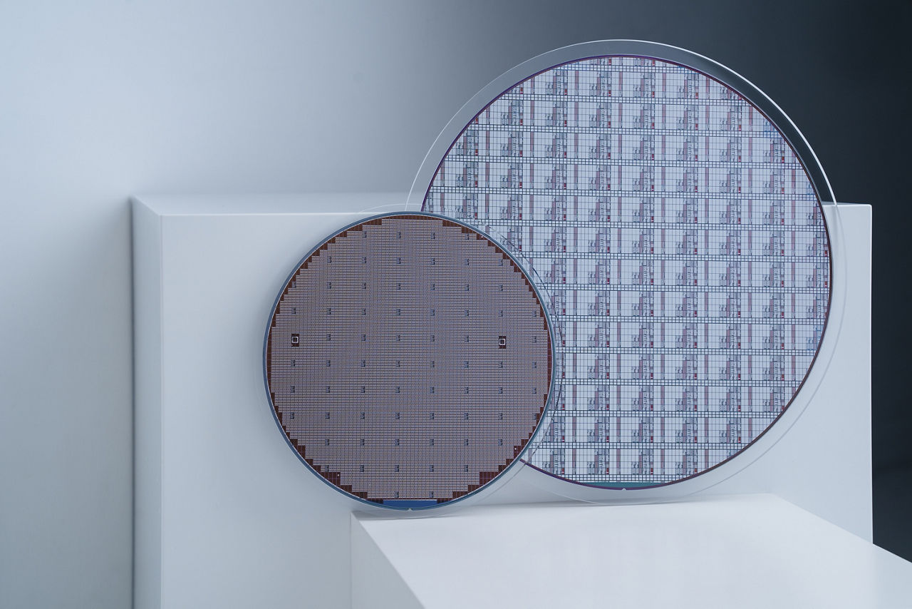
Gallium Nitride (GaN) transistors — whether grown on Silicon (GaN-on-Silicon) or Silicon Carbide (GaN-on-Silicon Carbide) — both leverage the high-efficiency advantages of wide-bandgap technology, but they differ significantly in cost, thermal performance, and ideal application focus.
GaN-on-Silicon — generally lower in cost and suitable for 10 kHz to 10 MHz applications in consumer electronics (fast chargers), data centers, robots and robotics, and automotive powertrains.
While GaN-on-SiC provides superior thermal management and high power density, making it the preferred choice for communication infrastructure that typically operates in the GHz switching realm.

GaN-on-Silicon & GaN-on-Silicon Carbide comparison
Despite their different substrates, both semiconductor materials share several core strengths. Both deliver high efficiency and speed, offering dramatically faster switching speeds (in the MHz range) and lower conduction losses (lower RDS(on)) than traditional silicon (Si) MOSFETs and IGBTs, which results in higher efficiency.
As wide-bandgap semiconductors, both use GaN for its high electron mobility and high breakdown field strength — roughly 10x that of traditional silicon — which allows for smaller, thinner GaN devices that can handle higher voltages.
Both also reduce parasitics by eliminating the parasitic body diode found in Si MOSFETs, which in turn eliminates reverse recovery losses. Finally, both offer greater thermal tolerance than conventional silicon, managing high temperatures better.
The core differences in the SiC vs GaN-on-Si decision span thermal performance, cost, integration, and crystal quality, as the table below shows.
While both configurations share the same top-level active regions to form a Two-Dimensional Electron Gas (2DEG) channel, their underlying structural support paths differ drastically to accommodate lattice and thermal expansion mismatches — which is where the GaN epitaxy diverges most.
The active region is identical for both: a thin Aluminum Gallium Nitride (AlGaN) layer is grown on top of a pure GaN channel layer. Because of spontaneous and piezoelectric polarization at this heterojunction, a high-density, high-mobility 2DEG channel forms naturally, without intentional doping.
The GaN-on-Silicon layer stack has to contend with silicon's massive lattice mismatch (~17%) and thermal expansion coefficient (TEC) mismatch (~56%) with GaN. To prevent the wafer from warping or cracking during cooling, manufacturers must grow highly complex, thick transition layers — such as stepped AlGaN layers or AlN/GaN superlattices — on top of the silicon substrate. This pushes the total epitaxial thickness to 5 µm–7 µm.
The GaN-on-SiC layer stack benefits from a much tighter lattice mismatch (~3%) and a closer TEC match with GaN. As a result, the transition region is structurally simple, often requiring just a thin Aluminum Nitride (AlN) nucleation layer. The defect (dislocation) density in the active GaN layer is significantly lower than in GaN-on-Silicon.
At Infineon, GaN-on-Silicon is used for both its RF and power products. While both product lines leverage GaN-on-Silicon technology, Infineon's RF GaN-on-Silicon and CoolGaN™ families are engineered for completely different physics paradigms.
The primary difference lies in their operating goals: RF GaN-on-Silicon acts as a high-frequency linear amplifier for processing complex wireless signals, whereas CoolGaN™ acts as an ultra-fast, binary on/off switch for raw electrical power conversion.
The two product families are tuned for different physics, as the table below summarizes:
Three optimization vectors set the two product families apart.
In RF GaN-on-Silicon, native GaN materials naturally form a conductive 2DEG channel, producing a depletion-mode (normally-on) device. This is preferred in RF design because leaving the channel unconstricted yields maximum electron mobility and maximum power gain at gigahertz speeds. CoolGaN™, by contrast, must be enhancement-mode (normally-off) so that it cuts power if the control circuitry fails — essential for power grids and electronics safety.
To achieve this, Infineon adds a specialized p-type GaN gate structure that modifies the energy bands to interrupt the 2DEG channel until a positive voltage is applied.
RF GaN-on-Silicon devices use advanced field-plate structures designed strictly to minimize feedback capacitance; lowering this capacitance prevents phase distortion and enables wide operating bandwidths, creating a stable, "Doherty-friendly" device for 5G waveforms.
CoolGaN™ devices are instead optimized for the lowest possible on-resistance (RDS(on)) per unit area to limit heat generation, and they are tailored for ultra-low output charge (Qₒₛₛ) to minimize energy loss when the transistor flips between on and off states.
RF GaN-on-Silicon is used in Doherty power amplifiers and envelope-tracking line-ups, where managing signal linearity, carrier-to-interference ratios, and Error Vector Magnitude (EVM) is crucial.
CoolGaN™ is deployed in resonant hard/soft-switching topologies such as Interleaved Totem-Pole PFC (Power Factor Correction) and LLC converters, where the absence of a body diode eliminates reverse recovery charge (Qᵣᵣ) losses entirely.
In RF GaN-on-Silicon, native GaN materials naturally form a conductive 2DEG channel, producing a depletion-mode (normally-on) device. This is preferred in RF design because leaving the channel unconstricted yields maximum electron mobility and maximum power gain at gigahertz speeds. CoolGaN™, by contrast, must be enhancement-mode (normally-off) so that it cuts power if the control circuitry fails — essential for power grids and electronics safety.
To achieve this, Infineon adds a specialized p-type GaN gate structure that modifies the energy bands to interrupt the 2DEG channel until a positive voltage is applied.
RF GaN-on-Silicon devices use advanced field-plate structures designed strictly to minimize feedback capacitance; lowering this capacitance prevents phase distortion and enables wide operating bandwidths, creating a stable, "Doherty-friendly" device for 5G waveforms.
CoolGaN™ devices are instead optimized for the lowest possible on-resistance (RDS(on)) per unit area to limit heat generation, and they are tailored for ultra-low output charge (Qₒₛₛ) to minimize energy loss when the transistor flips between on and off states.
RF GaN-on-Silicon is used in Doherty power amplifiers and envelope-tracking line-ups, where managing signal linearity, carrier-to-interference ratios, and Error Vector Magnitude (EVM) is crucial.
CoolGaN™ is deployed in resonant hard/soft-switching topologies such as Interleaved Totem-Pole PFC (Power Factor Correction) and LLC converters, where the absence of a body diode eliminates reverse recovery charge (Qᵣᵣ) losses entirely.
Discover the power of CoolGaN™ in action: our video showcases its real-world benefits, from increased efficiency to reduced size and weight to lower overall system costs.
Share in WeChat
Scan the QR code with your WeChat App to share this page.
What exactly are GaN-on-Silicon and GaN-on-SiC transistor technologies?
Both are wide-bandgap (WBG) semiconductor stacks that use a layer of Gallium Nitride (GaN) as the active semiconductor material for high-performance electron mobility. They differ in the base substrate wafer used to grow the GaN film — Silicon (Si) or Silicon Carbide (SiC).
Which technology does Infineon offer, and why?
Infineon offers GaN-on-Silicon. It uses GaN-on-Silicon technology for both the RF and power markets primarily to achieve massive cost scaling, volume manufacturability, and high electrical performance. Leveraging the mature silicon supply chain allows Infineon to produce advanced wide-bandgap devices at commercially viable price points. Both markets benefit from the fundamental properties of GaN materials — high electron mobility, high breakdown voltage, and high critical electric field.
In the RF market, the advantages include cost-effective 5G/6G scaling, enabling highly integrated RF Power Amplifiers (RF PAs) at frequencies greater than 6 GHz at a commercially viable price point, along with the efficiency and size benefits of the high power density required for wireless infrastructure while fitting into the strict size restrictions of active antenna systems (AAS). In the power conversion market, the advantages include higher efficiency and miniaturization — faster switching speeds radically reduce energy lost as heat and enable major size and weight reductions in power supplies, solar inverters, and automotive systems — plus advanced packaging, since GaN-on-Silicon, coupled with Infineon's advanced packaging concepts, minimizes parasitic elements for ultra-fast and reliable switching.
For more on where and why GaN is the right fit across these RF and power markets, see Infineon's Where, why GaN overview.
What are the key applications of GaN-on-Silicon in RF?
Across RF applications, GaN-on-Silicon supports several areas. In 5G infrastructure, the rollout of 5G networks demands efficient power amplifiers capable of operating in mmWave frequency bands, and GaN-on-Silicon enables high-power RF transmitters for base stations, providing improved efficiency and reduced system costs compared with alternative solutions.
In aerospace and radar systems — where defense and aerospace applications require RF components capable of delivering high power at frequencies ranging from a few gigahertz to microwave frequencies — GaN-on-Silicon amplifiers are being used to enhance signal range and reliability while minimizing power consumption. In satellite communication, where systems rely on high-power RF transmitters to maintain reliable signal transmission across vast distances, GaN-on-Silicon offers compact, high-performance solutions that improve efficiency and signal integrity.
And in wireless power transmission, GaN-on-Silicon is also playing a role, since high-frequency operation is essential for efficient energy transfer.
What are the key applications of GaN-on-Silicon in power electronics?
In power electronics, GaN-on-Silicon spans consumer electronics, with high-efficiency, ultra-compact chargers for smartphones, tablets, and laptops; automotive, including low-power auxiliary systems, wireless EV charging, and highly efficient on-board chargers (OBCs) for electric vehicles; data centers, with high-density power supplies and server racks that minimize energy loss and cooling requirements; and industrial and motor drives, including high-precision motor controllers for robotics, drones, and e-bikes that deliver smoother performance and quieter operation.
Where can I find Infineon's GaN-on-Silicon RF products and solutions?
Because Infineon's RF GaN PAMs and MMICs are proprietary ASICs (Application-Specific Integrated Circuits), access to their technical data sheets or evaluation modules requires establishing a direct corporate NDA with Infineon. Hardware developers planning a base station architecture are encouraged to get in touch.
What is GaN on SiC?
GaN-on-SiC is a wide-bandgap semiconductor stack in which a Gallium Nitride (GaN) film is grown on a Silicon Carbide (SiC) substrate, forming a high-density, high-mobility Two-Dimensional Electron Gas (2DEG) channel.
Compared with GaN-on-Silicon, the SiC substrate offers much better thermal conductivity (~370–490 W/m·K for superior heat spreading) and a lower lattice mismatch (~3%) with GaN, which yields better crystal quality and a structurally simpler transition region — often just a thin Aluminum Nitride (AlN) nucleation layer.
These properties make GaN-on-SiC the preferred choice for high-power, high-frequency applications such as macro base stations, radar, defense, high-power EV traction inverters, and industrial converters, typically in the GHz switching realm. The trade-off is a higher substrate cost and smaller wafers (typically 100–150 mm).
What is GaN on Si?
GaN-on-Si is a wide-bandgap semiconductor stack in which a Gallium Nitride (GaN) film is grown on a standard silicon (Si) substrate, forming the same high-density, high-mobility Two-Dimensional Electron Gas (2DEG) channel used across GaN devices. Its defining advantage is cost and scale: it leverages mature 200–300 mm silicon fabs and supply chains, allows easier monolithic integration with CMOS and 3D stacking, and benefits from the broad silicon ecosystem.
The trade-offs are a lower substrate thermal conductivity (~150 W/m·K) and a much larger lattice mismatch (~17%) and thermal expansion mismatch (~56%) with GaN, which require thick, complex transition layers. GaN-on-Si is generally suited to 10 kHz to 10 MHz applications and is used in consumer chargers, EV onboard chargers, data centers, small cells, and mid-band Massive MIMO.
At Infineon, GaN-on-Si underpins both the RF and CoolGaN™ power product lines.
Is GaN-on-Si better than GaN-on-SiC?
Neither is universally "better" — the two are optimized for different goals, so the right choice depends on the application. GaN-on-Si wins on cost, wafer size, manufacturability, and integration, leveraging mature 200–300 mm silicon fabs and easier monolithic integration with CMOS. GaN-on-SiC wins on thermal management (~370–490 W/m·K vs. ~150 W/m·K), crystal quality (~3% vs. ~17% lattice mismatch), and high-power density.
That maps directly to typical sockets: GaN-on-Si suits small cells, mid-band Massive MIMO, consumer chargers, and EV onboard chargers, while GaN-on-SiC suits macro base stations, radar, defense, high-power EV traction inverters, and industrial converters.
The decision comes down to matching cost, frequency, voltage, and thermal needs to the target application rather than declaring one substrate superior.
What is the GaN-on-Silicon process?
The GaN-on-Silicon process grows a GaN film on a silicon substrate, which is challenging because silicon has a massive lattice mismatch (~17%) and a thermal expansion coefficient (TEC) mismatch (~56%) with GaN. To stop the wafer from warping or cracking during cooling, manufacturers grow highly complex, thick transition layers — such as stepped AlGaN layers or AlN/GaN superlattices — on top of the silicon substrate, pushing the total epitaxial thickness to roughly 5 µm–7 µm.
On top of this, the active region is formed by growing a thin Aluminum Gallium Nitride (AlGaN) layer over a pure GaN channel layer; spontaneous and piezoelectric polarization at this heterojunction creates the high-density, high-mobility 2DEG channel naturally, without intentional doping.
The pay-off of this process is that it leverages mature, large-diameter silicon fabs and supply chains for cost-effective, high-volume manufacturing.